RETURN TO M3W HOME PAGE

INTRODUCTION
I have owned my Morgan three wheeler for two and a half years now and if you continue to read this page you will see that I have experienced many problems which I have attempted to solve in my own way. On looking back at my work and the description of that work, published here, I see that it has been very negative giving no credence to the positive experience of owning the vehicle. I would hate to think that anyone would be put off owning one by reading this page.Let me say, after two and a half years and 15,000 miles that this is by far the best motoring experience I have ever had. When choosing a vehicle for any journey, the Morgan three wheeler is my first choice. It is not much use if you want to carry more than one passenger or if you are taking sacks of rubble to the tip and it won't tow a trailer but otherwise it is unsurpassable. From the moment of unpopping the first fastener of the tonneau cover I start to smile inside ( and sometimes outside, but I'm not very good at that!). I fire up the engine and don't stop smiling till I close the garage door on the machine when I get home. "What happens when it rains?" they all ask" you get wet" I say - " think motorbike". They don't understand but I just curse out loud at the weather and keep the speed up to make the rain drops whizz over my head - smiling!
"Why three wheels?" You ask. Well, imagine a stiff rectangular plate, a beer mat is a good example. Lift one corner and prop it on a crown bottle top, the two corners on the other diagonal come off the ground. If this happened while your beer mat vehicle was going round a bend at speed you would find yourself in the ditch in no time flat. If it happened just as you came to a standstill you would not be able to pull away again. Why then, do four wheeled cars work at all? Because the suspension keeps all the wheels on the ground, the suspension has to be well designed and the better the design the better will be the road holding of the vehicle. The suspension on a four wheeler is working hard, all the time, compensating for every bump in the road. Now then, take your pocket knife - you do carry one, of course? - and cut the beer mat in to a triangle, prop one corner on the bottle top and your pub audience will gasp with surprise - the other corners remain in firm contact with the road. It can be clearly seen that a three wheeler will work with no suspension at all. Suspension is, of course, needed to make the ride more comfortable and to stop the whole vehicle form bouncing up in the air and going out of control but the three wheeler is inherently stable, just like the milk maids stool.
The Morgan three wheeler is not, perhaps, the fastest vehicle on the road, I often wonder at the ability of white vans to move along country roads as fast as they do, but the Morgan three wheeler is probably the most exciting and gratifying ride you will ever have. You will out accelerate almost everything, you will out brake almost everything and you will out corner almost everything. The Morgan three wheeler is a crowd puller which, if you like that sort of thing, is great. I love to sit children in mine while mum or dad take photos ( never forget those hot exhausts when children are around). I used to be afraid that I would have trouble finding it in car parks - no problem - it's in the middle of that crowd of people over there!
So, please, do not be put off by my hints tips and modifications, these machines will bring you much joy and many reliable miles with a smile on your face without any modifications whatsoever. The Morgan three wheeler is transport, it is a challenge and it becomes a hobby. Buy one, use it and show it off. If like me you love to tinker and improve then read on and please take what you can from my writing and do not hesitate to contact me if you want advice or feel the need to challenge what I have written or what I have done - I love to learn. I extend that invitation to all, including the three wheeler arm of the Morgan Motor Company, the owners of their wonderful vehicles, potential owners and anyone who is just interested. My contact details are at the bottom of the page - do please get in touch for a chat.
THE CHAIN DRIVE CONVERSION:-
1/ Reason for the project
2/ Liquid engineering
3/ layout
4/ bevel box
5/ Swing arm removal and refitting
6/ Machining the sprocket carriers
7/ Chain
8/ Alignment
9/ Mudguard
10/ first impressions
11/ parts and suppliers
CUSH DRIVE MODIFICATIONS
Modifying the cush driveThe trouble with crankshafts
The first big trial
Re mounting The Bevel Box
ENGINE REMOVAL PROCEDURE
ENGINE REMOVAL PROCEDURETHERE FOLLOWS A LIST OF MINOR BUT NONE THE LESS IMPORTANT MODS.
The luggage rack
The steering rack
The steering rod ends
The exhaust pipe and rectifier mounts
The pedal box
Greasing the prop shaft
Powder coating
Inner tube damage
addressing chassis cracks
The Cooling Fan
MISCELLANEOUS IMAGE GALLERY:-
miscellaneous image gallery
After each section, where appropriate, I have added an update to indicate the condition of the relevant parts of my machine as it passed through the 20,000 mile mark.
THE CHAIN DRIVE CONVERSION:-
1/ Reason for the project:- My 2013 Morgan threewheeler was purchased two years old with 635 miles on the clock. All the factory updates had been carried out at the expense of the first owner to whom I am greatly indebted. Brands hatch Morgans carried out all the work and delivered it to me like new. During the test drive I noted a bit of clunking as the belt jumped over the teeth of the pulley and they re tensioned it before delivery, all well and good
Subsequently the belt continued to jump teeth and had to be re tensioned almost every trip. After 7000 miles the rear sprocket was so badly worn that the threads of the side plate fixing bolts were visible and the belt stretched to the end of the adjusters. Those guide plates are another nonsense, they make so much noise when the belt rubs on them - and it does. Any belt, especially one which is no longer new, needs to be tracked under load, when the load comes off the belt will settle on a different part of the pulley and if we load it in the other direction it will move again. I return to the point that the vehicle puts too much stress on the drive system and so this problem becomes unbearable. I have read suggestions that one should continually apply washing up liquid to the belt to keep it quiet; what a lot of bollocks. My local dealer up here in Lancashire could not get a price for the elusive steel pulley and I was not sure that a steel replacement was the answer, after all the aluminium one was useless after only 635 miles. The only answer for me was to convert to chain drive. To quote one supplier " chains are for racing - belts are for holding your pants up" I could not agree more. While we may not be racing we are driving a vehicle weighing in at 500 Kg. the Harley Davidson, which I assume to be the source of inspiration here, only comes at weights between 250Kg. And 400Kg. and that for the fanciest of them. Research soon showed that there are numerous conversion kits available for the Harley Davidson machines, this speaks for itself. I resolved to put together a list of components and do the job myself.
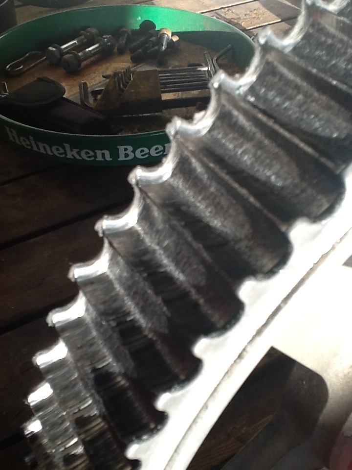
Here you can see the state of the rear sprocket after only 7,000 miles
BACK TO TOP OF PAGE
Back in the day I was taught to have respect for the next poor guy who had to dismantle a piece of equipment and I was encouraged to use a little tallow on precision fits and threads so that they came apart again easily and
without damage. Mechanical locking devices such as tab washers, lock nuts and split pins keep things from coming undone perfectly well. These days I use copper slip or any other of the off the shelf anti seize compounds;
a bit of grease or even, dare I suggest, tallow still works though.
BACK TO TOP OF PAGE
The project started with checking out how the chain and sprockets will line up and the solution is not too difficult to see. Machining the front belt pulley to carry a sprocket on the outboard side and the rear pulley to accept
one on the inboard side gets it all within a couple of millimetres and there is enough sideways adjustment in the swinging arm trunnions to cope with this. The original drive ratio is only just a fraction over 2:1 and so I
chose to use 24 teeth on the front and 48 on the rear. Some basic calculations backed up with advice from suppliers pointed me towards a 5/8 pitch chain 3/8 wide or a 530 chain, in modern parlance.
My bevel box was noisy. It was filled with a thick, black, presumably molybdenum disulphide based, lubricant. My inclination was to change this for a conventional gear oil and see what happened. Rumours had me think
that the reason for this was that a normal lubricant would blow out of the breather / filler plug. This is backed up by the change of position of the breather to the top of the box on later models. Mine was in the back of
the box centred on the output shaft. I erred on the side of caution and piped the breather up to a point beside the petrol filler pipe with the original breather plug inserted in the end of the rubber tube. I can now fill
from here with a syringe or squeezy bottle. I refilled with straight 30 oil as a flushing medium and changed for a good gear oil after the first twenty miles.
I suspected that the rubber mountings on the bevel box allowed some movement which may have contributed to the belt problems. Having ridden BMW bikes with sidecars attached I had a good idea of the upward forces
exerted at the front end of the drive shaft when accelerating ( the sidecar translates this in to sideways movement and it is quite scary till you get used to it ). I fitted up a video camera in the passenger seat and went for a
drive with the prop shaft tunnel removed and a plywood trouser guard to stop me from getting wound up in the works! The rising movement of the input flange of the box when accelerating hard is negligible so,
false alarm, no worries there. Although further, in depth, hands on study has proven this movement to be one of the biggest culprits in the drive chain.
BACK TO TOP OF PAGE
Before removing the swinging arm I took some measurements to enable me to mock up the swinging arm and bevel box on the bench later.
After removing the rear wheel and its spindle complete with chain adjusters plus the three clips for brake hose and hand brake cable, comes the task of retracting the swing arm trunnions. These are locked in place by two
rings requiring a "C" spanner to loosen them, a professional one at that. Mine covers the range of 1" to 2", made by Britool and is barely adequate I would recommend the 2" to 3" version. Do not assume that a cheap one
cut from steel plate such as those supplied to adjust shock absorbers will do the trick, it will not. The nuts on my machine were incredibly tight and glued in place to boot. Screwing out the trunnions all the way
( more glue here!) allows the swing arm to drop out of the frame, I supported mine with a rope from the roll over bars, a friend to hold it up would have been even better. I should note, at this point, that the plastic
plug which keeps the muck out and the grease in was missing on the drive side. It is not possible to remove the plug on this side with the bevel box in position nor to put it in if you forget to do so before replacing the
bevel box. I conclude that mine was missing from the factory or forgotten when the bevel box was out for the rubber mounting mod. Anyway the upshot was that the drive side taper bearing was shot and in need of
replacement.
Replacement of the swinging arm requires some caution as the bearings are back to back, which is normal for taper roller set ups but there is some flexibility in the front of the swinging arm fork and care must be taken
not to over tighten the trunnions. After setting the swinging arm almost all the way over to the drive side in order to get the sprockets aligned, I just tightened until all play was eliminated and then half of one flat or a
twelfth of a turn further, on one side only, to give some preload. Tightening the locking ring nuts was done with a 500mm long tube over the spanner handle and a pull of about 50kg on the end, not very scientific but
with their tapered seatings I doubt if anyone would want to take on the maths for torque wrench figures. I guess this is why they use the locking compound but I still went for copper slip, old habits die hard!
BACK TO TOP OF PAGE
After struggling with the front pulley retaining nut ( see para. 2) I did a quick hardness test on the pulley with a file, only to find it is like glass! The whole thing is hardened but the teeth are slightly harder than the rest
so operation 1 was to part off the teeth either side of the centre flange using a 9" angle grinder fitted with an ultra thin cutting disc. Followed by removing the remaining teeth one by one in the same manner.
I purchased 120 links and then cut it down to 116. (114 links will fit but does not allow for slackening the adjusters sufficiently to slip the chain off when removing the rear wheel). I riveted the chain joining link on the
bench and slipped it over the swinging arm while it was removed from the machine. The chain is 530 size from Tsubaki which comes fitted with X ring seals. I would have liked to have completely enclosed the chain in an
oil bath but there are too many odd shaped revolving bits to fit round and quite simply not enough room; as a result I have left the chain open but used ample mud flaps on the new mudguard ( in the style of " my other car
is a Land Rover"). This will keep the rear compartment free of horse and cow dung as well as keeping the grit off the chain. I am also tempted to fit a floor in this area to further exclude the harsh elements from the
workings but that will be at some later date. The subject of lubrication of open chain drives in harsh abrasive environments seems to cause much discussion but few conclusions are drawn. My thoughts are these:-
O or X ring chains seal in lubricant and exclude dirt but only from the pins and their mating bushes, not from the rollers.
Rollers must be lubricated from the outside, an oil bath is ideal but I have opted for regular manual application.
Oil, to be of use, must penetrate to the bearing surfaces inside the rollers and should therefore be of low viscosity.
Highly sticky, viscous oils will not penetrate well and help abrasive road dirt to stick in place on the rollers causing faster chain and sprocket wear.
I have chosen to clean the chain and lubricate with straight 30 oil from an oil can every thousand miles or so. If this does not give acceptable drive life I will try using no external lubrication which means less abrasive
clinging to the teeth and rollers.
Many comments have been made about the danger of the chain smashing through the bulkhead in to the cockpit if it should break. There is no centrifugal force to make the chain flail outwards. The energy in the top
run is purely linear. There is a great change of direction at the sprockets but due to the flexible nature of the chain this is not transmitted along the run. Sometimes, in machines with the final drive sprocket surrounded
by the gearbox casings, the chain will bunch up between the sprocket and the casting and due to the throttle being wide open much damage ensues. This can not happen on the Morgan. Motorcycle chains are nearly
always running just inside the riders ankle but we do not hear of accidents involving leg injuries due to chain failure. In my experience a broken chain just runs round the drive sprocket and lays itself on the road to follow
you along like some high speed snake.
BACK TO TOP OF PAGE
Sprocket alignment is of great importance for chain drives and so I did this before the chain was in place using a combination of straight edge, string line and good old line of sight. I have found no tolerances quoted by
chain manufacturers for sprocket alignment. Having got the alignment as close as possible I then made a hardwood " feeler" gauge ( in my case 52mm long ) to fit between the front of the wheel rim and the inside face
of the swinging arm at the front. The gauge can then be used to align the sprockets every time the wheel spindle is moved for whatever reason. Alignment of the wheel with the centre line of the vehicle is less important
as any discrepancy is made up for in the centering of the steering wheel while driving. I doubt if any noticeable "crabbing" will ensue from the small deviation that might result from giving more attention to the alignment
of the sprockets.
I purchased a fibre glass moulded custom bike mudguard and secured it to the aluminium factory item with 5 m5 nuts and bolts. On reflection I wish I had made something stronger but a regular check for cracks is not
too onerous. I then cut and folded some stainless steel side mounts to pick up the lower suspension unit bolts ( see pictures) this has resulted in a tight fitting and quite rigid set up.
BACK TO TOP OF PAGE
The first outing was short and resulted in the rear chain needing to be tightened up quite a bit. This is due to the fairly hard lubricant in the chain which, once run in, softens and allows the links and pins to assume the one
sided geometry which is the natural running state of the chain. Having tightened it to give approximately 10 mm up and down play in the middle of the top run with the bottom run tight, it has stayed that way. The bevel
box output shaft is very close to being concentric with the swinging arm bearings so, a tighter chain than might be expected on a motorcycle with the drive sprocket in front of the swinging arm pivot is quite acceptable and
welcome.
The end result of all this is quite remarkable. I now have a machine which is a joy to drive. The connection between the engine and the road is so much more positive and it took a while to get used to how much more
easily the back end would break away, the machine does not take prisoners when traversing a patch of gravel for example.
There is still some whine from the bevel box but at a lower pitch. I think this is due to the noise of the air being expelled from the sprocket by the belt teeth no longer being present. The noise of the belt scrubbing on
the side guide plates is, of course, history. There will be a bit of oil spray from the chain and the garage floor will show this up but I think this is better than all the aluminium and rubber dust emitted by the old drive.
As for longevity, only time will tell, watch this space.
With a few hundred miles now on the clock I am shocked to find that the initial problem still persists. With much higher loadings than previously, such as accelerating hard with a passenger on board and climbing a hill,
the same jumping and banging in the drive train is evident. Some people commented that the problem was not the belt drive but that something else must be amiss - they were right. I have made the machine more
pleasurable to drive, quieter, in need of less regular adjustment and all at a much reduced cost than the straightforward replacement of the original parts ( ignoring my labour, of course ). what I have not done is to eliminate
the original reason for the project - my machine still bangs and jumps in a way that makes me fear that damage will result if it is not eliminated. My research continues.
Here follows a list of parts and suppliers, if anyone decides to have a go at this modification then please feel free to ask any questions; my contact details are at the bottom of the page.
The total price for parts was a little over £200:00 and it took about 60 hours to complete, including time spent researching suppliers and pouring over web resources.
I am indebted to a gentleman named Chas. from B&C Express in Lincolnshire who spent some time discussing options on the phone and even sent a set of drawings of all the sprockets he stocked, for me to choose from.
You can find him on 01522791369
or via B&C Express.co.uk.
From B&C Express came the rear sprocket part No. JTR1871.48 and the chain -
Tsubaki Sigma XRS TX4 - ring steel - you need 116 links, I bought 120 to be on the safe side.
The front sprocket is a 24 tooth plate wheel with pilot bore and induction hardened teeth to accept a 5/8 pitch x 3/8 wide chain,from Cross Morse 0121 360 0155 or cross-morse .co.uk contact David Keatley.
The mudguard came from SGF Trikes, look in their E-bay shop
The shoulder bolts 10mm - m8 x 16 came from gwr-fasteners, E-bay again.
BACK TO TOP OF PAGE
In order to reduce or completely eliminate the slack in mid range I have removed the original rollers and made polyurethane blocks which completely fill the cavities between the inner and outer rotors.
Obviously my new Cush drive blocks are the cause of the change in vibration pattern but I wonder why it is there at such magnitude at all? One thing I noticed while the engine was out and the cush drive pulled apart was the
unusual layout of the shaft which carries both the cush drive and the clutch. Normal engineering design practice is to place the supporting bearings at each end of a shaft and the load or loads, between them. Think of a plank,
supported on a brick at each end - a bridge - you can walk over with confidence. now support the plank on one brick in the middle - a see saw - walk over with care because whatever you do at one end will cause an upset
at the other!
Overhanging loads
at the ends of shafts are usually only found on shafts with well spaced out bearings. Morgan have chosen to put one roller bearing near the centre of the shaft and the loads at either end, this is at odds with everything I have ever
been taught. At one extremity they have mounted the clutch, a mechanism, the normal operation of which needs good support to get it centered and balanced each time it is engaged. In the centre of the clutch is a support
bearing for the gearbox input shaft, I believe that the support should be provided by the shaft on which the clutch is mounted and the gearbox shaft is the one supported, not the other way round. Normally the clutch is mounted
on the end of the engine crankshaft, a solid shaft with good bearing support from the main bearings in the engine. At the other extremity of the shaft they have hung the centre rotor of the Cush drive, a mechanism which has no centring or
supporting function at all and is, indeed, designed to be flexible. I assume that varying loads are brought to bear on the centre rotor due to the rubber rollers not all compressing in a uniform and precise manner; in laymans
terms " it probably wobbles about all over the place". No criticism of Centa here by the way, that is just what it supposed to do. This revolving seesaw could result in early failure of the bearings which are under a variety of
confusing influences although I have read no reports of this to date. I also think that it may be the source of some of the vibration.
My answer is a relatively quick fix compared to the proper answer which would require a new shaft with a longer nose and a redesigned outer rotor for the Centa drive which would house a plain bearing to support the
longer shaft.
It should be noted that the Centa drive unit is designed to run between a marine prop shaft and the output shaft of the reduction box on the engine, both of which are well supported on properly spaced bearings. The barrel shape
of the rubber rollers allowing for out of alignment due to the difficulty in accurately aligning the engine and the stern tube which are mounted far apart in the hull. Our Morgan's hopefully have no need of this.
I have made an aluminium bearing carrier, machined from a billet, and this fits accurately in to the recess in the back of the Centa drive outer rotor.
A short steel stub shaft replaces the retaining washer for the centre rotor and is a light interference fit in the end of the rotor. This " nose" is supported in the Oilite bush.
To make a little more space to allow maximum supported length for the stub shaft I have left out the front plate from the inner rotor and its fixing bolts. The face of my new bearing carrier will provide a sufficient end stop for the
polyurethane blocks.
I now have a shaft with a decent spacing between its bearings which support the Centa drive between them and which provide better support for the clutch and gearbox shaft at the other end. Will this result in less vibration????
In removing the Centa drive rotor from the end of the crankshaft ( 3/4 Whitworth or 33mm. Socket ) I found that it was not as tight as expected and had, ( surprisingly! ) no locking glue to help hold it but a shake proof washer
fitted on top of a very thin plain washer which was seriously distorted. Shake proof washers need to bite in to the nut and the thing being tightened on to, putting a plain washer underneath stops them from working. Why then
are they so often fitted with a plain washer? I could rave on about proper apprenticeships but maybe elsewhere. Mine will be replaced with a thick machined washer, no shake proof washer and properly tightened. There is enough
spare shaft thread for a nylock 7/8 x14 tpi UNF. nut if you prefer.
Pulling the outer rotor off was not too hard but needed a strongback in the form of a square steel bar with holes in to pick up two of the M8 holes in the face of the rotor (see picture below) and a central one for a jacking stud.
I would suggest 25mm square.
I believe that the origin of the problem is the wheel skipping on the road surface; a symptom of which is the jump and bang in the transmission. Having eliminated almost all of the slack in the system, I have also eliminated the
noisy symptom. One might liken it to a blacksmith holding his hammer an inch or so above the anvil and then bringing his fist down hard on the hammer head, the hammer will move down sharply and bang against the anvil.
If the hammer is then allowed to rest on the anvil, thus eliminating any possibility of movement, (no slack in the system) when the fist impacts the hammer head it will not move and there will be no bang.
So then, my conclusions - the banging is not caused by the toothed belt, it is not caused by the Centa cush drive unit, nor by any other part of the drive train, it is caused by the back tyre skipping on the road surface.
The symptom, however - the banging - is definitely the result of too much free play in the drive train. this free play is mainly in the cush drive unit, also in the unstable cush drive shaft with its misplaced bearings and
to some degree, in the toothed belt final drive and aluminium pulley which due to ingress of road dirt wear out prematurely and are seldom in prime condition.
This has been a long journey but one with a most satisfying result. At last my five speeder behaves like a £ 35,000 vehicle and not like the " bag 'o nails" it was when I first bought it! My next expedition is to be a round trip
to visit many old friends near Exeter, Paris, Dijon, Rotterdam and Sheffield, in that order; watch this space to see how the vehicle performs.
I resolved to sort the issue out and did not sell any more kits til I had the answer. Much research has brought me to the conclusion that using a tight fitting, splined driving joint is a very poor design choice. When a gauge or hub are tried on the shaft,
if one spline is slightly too big or out of position then neither a gauge nor a hub will go on even though the rest of the shaft may be undersize - a nonsensical situation which can not possibly result in good sizing of the shaft. This will also frustrate the
efforts of the motor fitter who may think that a hub is a tight fit even though 90% of it is loose. I also noted that some of the shafts had been hardened by the nitriding process but the large majority of them had not. All of which results in a shaft that may
be undersize and is not of sufficient hardness to resist wear. The only way to ensure success turns out to be the return to my original technique of custom hand fitting of the unit here in my Lancaster workshops. A 10% failure rate is not acceptable and this
is the only solution I can see.
I realise that this creates problems for overseas customers who would normally buy on line and fit DIY fashion at home. It would be good to find someone willing to do the hand fitting remotely but difficult to find the right man from here. It is also unfair to
put the responsibility for a successful outcome on the head of the installer so I am afraid the job will remain in house here in Lancaster. If you find yourself wanting or needing my upgrade then it costs only £250.00 or so, plus insurance, to do the shipping of the engine -
both ways and I will turn the job round very quickly.
Further research has led me to believe that the original Centa hub is also fitted using questionable engineering practise. All of the hubs I have examined - and there have been many, are of soft material and an extremely poor fit. (See the picture below)
I have had to carry out quite a few repairs to worn, twisted and broken crankshafts and it seems that Harley Davidson engines with identical crankshafts suffer similar problems so I envisage more of this work in the future. Witness this screen shot below -
Thanks to Zippers performance for permission to use this.
https://www.zippersperformance.com
Twisted and broken shafts have to be repaired by grafting a new shaft in to the crank web.
Easy drive mostly on motorways with no noticeable problems save for the development of a bit of vibration at about 3,000 rpm. This is, strangely, greater in top gear and annoying because 70 in 5th. Is just at that point.
There was very little vibration evident on a trip to the club meet at Garstang last night. Huge improvements in performance on smaller country roads, no clattering if you get the gears wrong. It will pull from just over
1,000 rpm. with the clutch fully engaged in the first three gears, you can even pull away from a standstill in third. There is nothing so satisfying as pulling away really fast on an engine that sounds as though it is barely
off tickover.
What a crazy journey! Started from Richard's at 11:00 with advice to take the old bridge over the Severn - a much nicer route. Stopping for petrol just outside Ross on Wye I was surprised to see an ash green five
speeder go by, I still had to pay for the fuel so no chance to catch it - damnn. Got to Tintern abbey only to find the road closed. Turned round and followed a diversion at least 20 miles long which brought me to
Chepstow where surprise surprise, the bridge was closed. Never mind down to the M4 and take the new bridge - no charge to leave the country, fortunately. Then on to the M5 which was nose to tail with frequent
stops in the fast lane! Tried to stop for a pee and a bite to eat at the services - couldn't find a parking space so back to crawling down the M5 to Exeter where I arrived at 3:30. Still and all, thanks to Jess and Richard
for their hospitality and fine food. Jess introduced me to butter on porridge - wonderful - thanks Jess
The vibration seems to be a bit worse but has stayed consistent so I don't think anything is damaged just settling down / bedding in or whatever. I really need a ride in someone else's machine to remind myself of what
it was like before, I wish I had made notes! Lots of opportunities to pull away hard after standing still in the fast lane of the motorway, caused, on one occasion, by a guy retrieving one of his trailer wheels from the fast
lane after it had somersaulted over the moving traffic, miraculously missing everything including me! No banging at all, it seems now only to happen two up under extreme acceleration whereas before it happened all the
time. Still very pleased.
Good fast run with no hold ups at all. Vibration at 3,000 rpm is worse. I begin to wonder if my extension stub shaft has come loose; I can't think of anything else that would fail. The machine feels now like it did with the
new polyurethane inserts but not the support bearing - puzzling.
The reclining seat on the ferry is not really comfortable enough for an old man for 8 hours but I got some sleep so all is well. Despite offers of hospitality in Paris, made on the Talk Morgan forum, thanks guys, I have been
talked in to going straight south to a warm bed just north of Dijon.
Off the boat at 08:30 - French time. A misty moisty morning if there ever was one, a bit like flying in and out of clouds and no scenery visible. Having made good progress once clear of the town, I stopped for petrol
and to buy some breakfast. On pushing the starter all I got was click, click, click from the starter motor, enough power to engage the bendix but not enough to turn the motor. A friendly motorist came to help and ended
up taking me to his pet mechanic in the Peugeot garage behind the supermarket. Nice man came out and jump started it - no trouble. I took it to his workshop and he tested everything with a multimeter - all working
fine - and still is - strange. The nicest thing was he didn't charge me just wished me "Bon vacance" and waved me on my way.
The rest of the 11 hour drive was wet but uneventful. Breakfasted on brioche with chocolate chips and a banana and washed it all down with fruit juice, how horribly healthy. Vibration still the same and seems to be
coming from behind me. So now I begin to wonder about the rubber mounting kit which has been fitted to the bevel box. I have not studied the set up, does it use the same poor quality rubber mounts as the rectifier
and exhaust pipes? Get under and have a look in the morning.
I must also have a look at the tyres, I found the back wheel breaking away much too easily in the wet, I think a different tread pattern may be in order. While having a pee in some motorway service station I saw an
advert for a new Michelin tread pattern, the Michelin cross climate XL, for all weather use which seems to be nearly symmetrical, that could be interesting. The front brakes are none to pleasant in the wet either, the
left one does not work when first applied giving the machine a nasty kick to the right till the water has been scraped off. Why only one side I wonder? On to open up my house and do some little jobs - prune the trees,
cut the grass, fix a neighbours 2cv!
All neighbours visited, rear chain oiled, checked everything was still in place after bouts of vibration, look at tyres and brakes - all well - 836 miles and about half way round the trip, onward in the morning.
Fog and mist again on the way north. After mid day the fog cleared and the sun won the battle to warm me up. Some great scenery and lovely quiet country roads going north from Reims towards Arras and a stay with
friends John and Debbie. The vibration has settled to a level which is constant and unacceptable; I change gear frequently to avoid it. One scary moment when my eyes, being low to the ground, were just level with the
road surface ahead and all I could see was a sea of roadside grass into which the Tarmac disappeared well inside my breaking distance. More rubber lost from the tyres!
Soft bed, warm food and a panto rehearsal with Debbie and John, you can't say my trip was anything but varied!
Good weather and fast country roads till a clattering from beside me announced the failure of both exhaust mounting rubbers on the right pipe. I grabbed the thing up from the road and coasted to a halt in a farm
gateway. I was surprised at this because the factory ones were replaced with good quality ones last time the engine was out. Being a good Boy Scout, I had a length of fencing wire in the tool box and so I was able
to wire it back in place quite securely and continue on my way. I noticed the broken faces of the rubbers were not in line; the pipe seeming to be about 15mm. rearward of its proper place. Something else to investigate
when I get home. I arrived in the industrial end of Rotterdam without further incident. Well looked after here by old friends from the sixties who are my surrogate family in Holland - home from home.
On Saturday I went with my Dutch " brother" Aad to meet some guys from the Dutch Velocette owners club some 60 km. north of Rotterdam and noticed that with a heavy passenger the vibration seemed less severe.
Could this be because of the extra inertia in the vehicle body or is it to do with the extra torsional load in the transmission? A little bonus was the arrival of a couple of four wheel Morgan drivers who had picked up on
our presence in the car park and came to see a three wheeler in the flesh. We had quite a little party!
Fog and heavy traffic getting out of Hull. Engine went in to skip fire mode several times but dropped out of it again as soon as I pulled away. An indicator light to tell when the cooling fan kicked in would have been nice.
I have since learned that the fan is easily heard over the engine so it seems that mine is not working; add to this the fact that skip fire should be disabled when the kit is fitted and my displeasure with Morgan dealers is
greatened! Great drive through the dales in glorious sunshine everything going like clockwork now, except for the vibes at 3,000 rpm, that is. Got a bit lost due to roads still out after last years floods and arrived home
about 2 pm. 9,996miles on the clock which means 1,660 since leaving Lancaster eleven days ago; a pretty good test on all sorts of roads and at all sorts of speeds. Prolonged motorway stretches at an indicated 90 mph
( the sat nav says this is just over 80 ), lots of hard driving on country roads and a good bit of shuffling along in jams. Brilliant sunshine, fog and pouring rain - loved every minute of it.
.
All that remains now is to open it all up and see what it looks like. I suspect my extension stub shaft in the Centa drive has vibrated loose. If this is the case then I think a larger diameter, finer pitch retaining bolt will be
called for. We shall see but not for a week or two as I have flutes to prepare for the early music exhibition in Greenwich - whatever happend to that retirement plan?
At about the time of Claire's accident I had a day out comparing my machine with a more standard version and was surprised by some of the results. My machine has developed a fierce vibration at about 3000 rpm. With
worthy assistance of my co driver, a stethoscope and some real hands on ( literally ) research, I identified the vibration source as being the front of the bevel box lifting by about 3mm when accelerating but more
importantly, at 3000rpm under load, that lifting becomes a high frequency up and down oscillation. This causes the same frequency change in the chain tension and therefore a vibrating drive to the back wheel. Sorry
if this is all a bit difficult to follow but it is not easy to describe!
Now then, the real surprise, when I went looking for the same symptoms in my colleagues unmodified machine - there it was - just the same as mine but with original Centa parts and a good condition belt final drive.
It should be noted that the unmodified machine was much nicer to drive than mine was when I bought it with only 650 miles on the clock, I guess mine was just one of the worst examples - but not unique in that
respect, I am sure. Why has the vibration come back after such a promising start? I wonder if the silicone lube that I used to make the Centa coupling easier to assemble made it a move a little easier internally and
now that it has dried out the grab of the polyurethane in the cavities makes it all a bit stiffer. Hmmm.
My conclusion is that much of the trouble in the drive train stems from flexibility of the forward mounting boom ( or is it a beam? ) of the NVH kit. I intend to brace the front of the bevel box so that it can no longer lift.
If this works then I shall remove the NVH kit altogether.
January 2017 already, how time passes when one is old! A short lived experiment to hold the front of the bevel box down has shown the problem in its true colours. I fitted a new bridge between the chassis tubes under
the front of the bevel box, removed the forward beam of the NVH kit and fitted a single fail safe rubber engine mount under the bevel box nose. On taking it out for a test drive the banging became so severe as to make
the machine undriveable. The lifting force on the bevel box front mount had almost turned the rubber mounting with its steel flanges inside out! No wonder the NVH kit is not strong enough to hold it down. On close
inspection one sees the clamping arrangement at the front of the box to be very poor indeed. The original bolts hold the beam to the bevelbox casting well enough but the forces here are great and I have seen a picture
of one of the early versions with the vertical weld, where the triangular gusset fits, completely broken through. To reinforce this the gussets have been lengthened and a box built round the front flange of the bevelbox
casing. Bolts are then fitted through the access holes in the flange to clamp it all up. Firstly, the box is rigid and so the clamp bolts can not possibly work and secondly the front bevelbox flange is cast aluminium and
has mould release tapers incorporated so a rectangular box will not tighten on to it anyway. I will leave you to imagine the loud clang as this heavy piece of nonsense lands in the skip!
A possible further complication is a phenomenon known in the oil industry as " soft foot ". This is a situation where the foot of a piece of rotating equipment does not land precisely on its mounting pad causing distortion
of the castings when the holding down bolts are tightened. This in turn causes poor alignment of bearings and shafts within the equipment, early failure and noisy running are the symptoms. This may or may not
contribute to the noise of the bevelbox but it makes me wonder.
My solution to all this has been drastic, the rear, transverse member of the NVH kit has followed the front beam in to the skip and I have built a new " NVH" kit of my own design. I worked on the principal that I should try
to isolate high frequency bevelbox whine from the chassis but not sacrifice strength in the mountings. If the original mounts were sufficiently strong and I am to reduce this with some flexible, vibration absorbing material
then I shall need something extra to regain strength - I have employed geometry not " beef". The front mount is now a bridge like the original but to make fitting easier and not require the use of grinders and welders
close to petrol pipes; it clamps on just forward of the point where the Morgan dealer hacked off the original mount. The rear one is similar to the original but again, is clamped in place round the chassis tube.
The geometry comes in to play with a mounting taken from the top bevelbox casing bolts, upwards, to the transverse chassis tube behind the seat backs. Having seen how powerfully the front of the bevel box rises
on hard acceleration I feel that the forces transmitted to the bottom chassis tubes are possibly great enough to cause cracking at some point; the third, top, mount helps to spread this load and may prevent future problems.
All three mounts are clamped to the chassis tubes with a 2.5 mm. thick
polyurethane liner, in the clamps, to isolate gear noise from the chassis. The photographs below will help make this clearer.
I have always thought that Centa should have put more research in to the shape of the recesses in the two rotors of the unit but that of course would have involved some expense in machining up different rotors till
they got it right and I do not think Morgan would have found time to put in the miles to test each one in a vehicle ( I would expect at least a hundred hours of realistic road driving per version ). I doubt if Centa could
have come up with a sufficiently realistic test bed.
The simple alternative is to experiment with different shaped inserts, cheap to make on the band saw and infinite variations possible. The biggest expense being labour ( hauling the engine out for every change).
Up till now I have only been thinking about different degrees of hardness for the polyurethane inserts. A vee shaped cut out at each end of the insert, making it in to a sort of bird beak, has given me softer take up
as the " beak" is closed and provides progressively harder resistance as the power is applied. This is much the same as Centa first intended but not quite so sloppy as their round barrel shaped inserts.
I had a hub made from alloy steel and using the same production technique as is employed for the manufacture of gas turbine blades it is fitted to the driving flank faces and both major and minor diameters.
The new hub is a shrink fit in the bored out Centa coupling and employs two taper pins and stronger alternator rotor fixing bolts to ensure the integrity of the assembly.
I have had no further trouble from this arrangement. I have had reports of such failures with and without my upgrade fitted. I now recommend anyone removing the coupling to carry out this modification.
It is not certain that the centa unit will fail in this way, in fact I have one customer with over 30,000 miles on the clock with my upgrade and no sign of trouble, The choice is your's but I think the cost of stripping out the
unit for a later repair says it all.
My thinking about this problem has brought about the third stage of my modifications to the drive train. turning the rotor round would do the trick but would mean a redesigned shaft which would be quite expensive and would
also loose the recess where my new support bearing shaft is located. The alternative is to machine away the fixed flange of the inner rotor and replace it with a removable one the same as the one on the front end. I no longer use the
front end flange because retention of the inserts is provided by my support bearing carrier, so, I just use the old one at the other end. removing the flange allows the inserts to be slid out for replacement - surely this was Centa's
intention. There is scant space for this to happen and I have had to optimise the length of the inserts. reducing them to 58mm. in length, a reduction of 2mm. If original barrel shaped inserts are used they must also be reduced in this
manner and a small hole needs to be drilled to make pulling them out far enough to get a grip on them possible. The only snag is that I can't get in there to do it, so a hole has to be cut in the bell housing. I have utilised the hole,
put in to grease the original Harley style cush drive, and I have extended it back to the flange of the bell
housing - this makes it just big enough to get a hand in to remove the inserts. Does this weaken the casting to any significant degree? the bell housing is fixed to the crankcase at one end by 4 x 5/16 ANC. screws - the original fixings for the
primary chaincase I believe. The other end of the bell housing is secured to the gearbox with 7 x M10 bolts an enormous disparity, I do not think that a little reduction in material at the gearbox end will make a jot of difference.
Replacement is a tricky job requiring good dexterity and preferably, small hands. I can do the job in about half an hour and my hands are pretty big - Claire can
do it in less time than me. why didn't I think of this two years ago? The advantage of being able to inspect the inserts thoroughly before a long run is enormous!
You would be well advised to read through this a couple of times before you start
You are going to remove fuel pipes, have a fire extinguisher standing by.
The engine is heavy, you will need an engine crane or overhead gantry and somewhere to put it when it is out, maybe a sheet of plywood with some blocks of wood forming a cradle to stop the engine falling over.
You will need a 5/16 Whitworth socket spanner.
A hardwood stick about 25 x 50 x 500 will be useful as a drift and lever on some of the tighter bits and pieces; it will not damage the paintwork or the ends of threads when drifting out tight bolts. Take a felt tip pen and write the words
" very useful stick" on the side of it and hang it up in the workshop - you won't regret it.
You will need new clips for the petrol pipes. The jubilee type of clip is not very good on small sizes due to the inflexible tightening device, you should look for the ones with a nut and bolt through the ends, they are numerous
on e-bay and inexpensive.
You will need some cable ties to replace ones cut off when dismantling.r
You would be well advised to have some new ( better quality ) mounting rubbers for exhaust pipes and rectifier mountings. I get mine here vibration-mounts
After removing the bonnet and disconnecting the battery earth lead ( when you re-connect there will be a slight sparking from the current draw of the electronikery be aware of any petrol fumes or leaks from the disconnected
fuel pipes). I lifted the front of the vehicle and supported it on axle stands under the forward chassis members. Don't forget there is only one wheel at the back so the vehicle is quite unstable if you jack it in the centre at the
front!
The next task is to remove the oil pipes and if you are ready for an oil change drain the oil out into an old container. The lower one is the feed and this is where most of the oil drains from. Don't get them the wrong way round
when refitting. If not changing the oil put plugs (14 mm diameter wood with a taper at one end worked for me) in the ends of the pipes and tighten the clips.
Take out the two bolts holding the cooling fan and after un plugging the cable ( note which wire goes where, I am not sure if they are interchangeable) lift it off being careful not to loose the aluminium sleeves from the bolts or
the bits of rubber hose which hold the fan housing away from the cylinder fins. You can now use the fixing bolts to hold some sort of lifting bracket of your own devising, I use a chain with the end links bolted down with big
washers. The chain needs to be at least 600 mm long to avoid putting too much sideways force on the bolts, we don't want to be bending them. A rigid bar with a ring welded in the centre might be a stronger option but the
chain works for me. Whatever you use make sure the bolts are tight and don't forget, this is a heavy engine.
Use a small chisel to flatten the locking tabs on the exhaust pipe flange nuts and remove the nuts. You will get one more go out of the locking tabs. It is now that you will discover the poor quality of the rubber mounts used for
the exhaust pipes and for the rectifier heat sink. It would be best to have some better quality ones standing by. It is worth the effort of removing the pipes completely to get some space. Un plug and un clip the gas analyser
cables first. I have replaced the flange studs and nuts with 5/16 18tpi UNC x 11/4 long socket cap screws in stainless; they make a neater job and there is not really enough clearance for the socket spanner to undo the hex nuts.
Drill and wire them - no need for fancy tab washers then.
Next is the steering rack, remove the bolts through the rose joints from the front wheel steering arms and turn the wheels outwards. Remove the two bolts which hold the rack to the sloping support members. It is a good idea to
check how easily they come out, especially if you have the retro fitted cross member which actually forces the supports on my machine further apart. I have drilled them a bit over size to make up for this, otherwise it can be almost
impossible to get them back in. Take out the bolts and nuts from the upper and lower ends of the supports, you will need to take the top nut off the suspension unit bolts to get the bolts out. Then push the supports backwards
at the bottom to get them off the chassis eyes. Juggle them out to the side and allow them to hang on the brake pipes. Remove the steering column clamp taking the bolt right out, as it goes through a groove in the rack input
shaft as an added safety measure. When you replace the clamp you may want to set the steering wheel up with one spoke vertical at the top so that you can see the tachometer and fuel gauge. Now for the tricky bit, the rack will
come out even with the retro fitted cross member in place; swivel the rack back(anticlockwise from the right hand end) till the input shaft is underneath pointing forward and slightly down, the rack can then be massaged out to
the right (drive side) - persevere it will come out!
To the top of the engine now, remove the fuel pipes, marking them left and right for re fitting, you will need new clips. The jubilee type of clip is not very good on small sizes due to the inflexible tightening device, you should look
for the ones with a nut and bolt through the ends, they are numerous on e-bay and inexpensive. The third, smaller, pipe has no clip, just pull it off and spit on it before pushing it back on later. No fuel will run out if you don't let
the pipe ends fall down to the ground. For safety you might like to plug them off.
Remove all of the electrical plugs, they are numerous but with one exception, all different so it is not possible to get them wrong on re assembly but a photo might speed things up. Don't forget the ones on the alternator/rectifier and oil filter
housing or the feed to the starter solenoid. Most of them have a security clip which has to be lifted with a thumb nail before pulling them out, don't use force! Pull the HT leads off the spark plugs. Remove the knock
sensor from behind the inlet manifold on the right cylinder, don't loose the thick seating washer behind it. The two wires on the fuel injectors have a wire clip which can be slid out with the tip of a screwdriver, don't launch them
across the workshop never to be seen again ( tie a length of thread round them to be sure) Update - I have learned through trial and error that these plugs come out when you push the wire clip further in so there is no risk
of loosing them. and mark the plugs left and right; these are the ones that can be fitted to the wrong side.
The throttle cable is a fiddle, take out the two screws holding the fixing bracket, leaving the outer cable wired in place. Use a length of string with a loop in the end to loop over the little knob on the disc and pull the throttle
wide open, tie it in place. You can now feed the slack cable inner down far enough to twist and remove the nipple, note which hole it goes in, there are two.
Remove the earth strap from the top starter motor bolt but leave the starter in place. Strangely this bolt and those in the bell housing require a 5/16 Whitworth spanner. The live feed will be easier to remove when the engine is
moved forward an inch.
Remove the rectifier and its mounting plates ( there must be a lighter way of fixing this thing to the vehicle ). The powder coating on mine, and also on the headlamp brackets is completely shot and I will have to repaint them.
I have removed a bit of steel from the lower half of the intermediate plate to get some weight off. A better mod would be to make a new rectifier back plate in aluminium with the top fixing hole built in.
Remove the oval plastic sensor from the front bottom right of the crankcase and put a wad of paper in the hole to stop any dirt getting in.
Tie all the cables and pipes back out of the way with a length of string.
Take the weight of the engine on your engine crane or block and tackle being very careful not to lift the vehicle and dislodge the axle stands. Now remove the engine mounting bolts - three each side in the bell housing, two each
side holding the engine to the mounting plates and two through the rubber mounts in the chassis. The plates will not come out at this stage but will fall out on their own when you lift the engine later, remember this when you
come to reinstalling and be prepared for a struggle getting them in place.
At this stage you should decide wether or not the gearbox should come out as well. The pros and cons are these :-
If you leave the gearbox in you will have to drill the body panels as described below to separate the bell housing. Update - This has proved to be unnessecary see below.
The engine is lighter to handle without the gearbox attached and it balances better on the lifting gear.
Taking the gearbox out means disconnecting the clutch hydraulic hose which in turn means removing the oil tank to get at it for bleeding when you put it back and the plastic connector pipe is very
vulnerable while the engine is swinging about on the crane to get the right angle for removal - I know, I snapped mine off - made by Volvo, part no P30787652 for a CX 9 - Just in case. It is very easy
to do a gearbox oil change while it is out and very difficult in situ.
If you decide to take gearbox and all, remove the oil tank and hoses. It also helps to do this if you leave the gearbox in but it is not essential. Mark the hoses for replacement but if in doubt the one from
the bottom of the tank goes to the fitting marked "S" on the crankcase. Disconnect the clutch hydraulic hose by pulling out the spring clip with snipe nosed pliers and pull the hose out of the plastic
connector - plug both sides to prevent loss of fluid and ingress of dirt. Remove the connections from the neutral indicator switch. Remove the prop shaft and make a hollow bung to replace it or you will
loose all the oil on the floor - or you could drain it first but it is nicer to be able to re-fill while the box is on the bench. Remove the three screws holding the gear selector lever in place and lift the lever
out - the turret in to which it fits should be filled with gear oil when putting it back but I can find no mention of level - I just filled to the top of the socket in to which the nylon button fits. Take the weight
of the gearbox on a trolley jack and remove both top and bottom fixings from the rear rubber mount. Now CAREFULLY slide the whole unit forward watching the clutch connector pipe as you do so.
Go to "the engine can"
The bell housing bolts come next, place a jack under the gear box just sufficiently to take the weight of the box and no more ( don't lift the whole vehicle off the axle stands) two socket cap screws are fitted from the front at the
bottom. The rest are hex head bolts, 5/16 Whit. again. The long one goes in the top hole. To reach the one on the left side and the two on the right side I took a hole saw to the plastic body panel ( see picture ). The mechanics
at Brands Hatch Morgans did it without resorting to this but it was beyond my ability with the tools available. Update - If you take out the bolts securing the plastic panel to the chassis tubes
And then cut along the mastic seal top and bottom the panel easily flexes out enough to get an extended socket spanner (5/16 whit ) on the bell housing bolts.
The front two bolts and the vertical mastic seam can be left alone. I do not find I need to re seal the mastic but you can if you prefer.
I, later, took out the screws holding the two side panels and discovered how the dealer mechanic does the job. They remove the first two screws and then prise the panels back breaking them at the point where the very strong
mastic seal commences; when the screws are replaced the break is almost invisible - good eh? If you look carefuly at the picture above you can just make out the cracks extending up from the bottom edge of the panel.
The engine can now be pulled forward and slightly lifted ( don't lift the whole vehicle off the axle stands). The two tubular dowels are quite tight and may require a bit of CAREFUL leverage. Don't loose them if they fall out.
Remove the starter motor cable now.
If you are doing an oil change it is easier to change the filter while the engine is on the bench.
If you are to remove the clutch and the plate to expose the crankshaft shock absorber coupling this can be done by loosening the fixing bolts a bit at a time through the holes in the starter gear. There are three jacking screw holes
in the flange to help pull the coupling rubbers out but I did it with my fingers.
Putting it all back together is just a reversal of these operations but be prepared for a bit of time wasted juggling the engine mounting plates, these need to be got in place before the engine is bolted back up to the gearbox bell
housing. When replacing the engine swivel it a bit to allow the starter motor to go between the chassis members first. It helps to put the top bolt in LOOSELY to act as a guide when locating the tubular dowels.
The steering rack with its support bars are also a faff.
Don't forget to fit the starter cable before the engine is all the way in.
Replace any cable ties which you may have cut off. Don't replace the battery earth lead till last and be sure there is no petrol about when you do it.
The clock will need to be reset but the mileage and trip meter readings are unchanged.
If you drilled holes in the bodywork a simple fix is to stick a bit of plywood over the holes with silicone sealer, hopefully you will not have to take it off again for a long time and when you do, a sharp flexible blade will do the trick.
When tightening the engine plate bolts leave the ones through the rubber mounts till last.
don't forget to tighten the top suspension unit bolt.
BACK TO TOP OF PAGE
Being a motorcyclist of long standing I have a penchant for pannier type cases and more to the point I had a pair in the garage. White - well they used to be - Golden Arrows from Craven.
A little research and I found that they still make motorcycle luggage so I ordered a top box to make up the set. A coat of black paint, some new fittings and catches and all I needed was a rack to mount
them on. I have to say that the latest equipment does not have the solid feel of the old stuff and the lock on the top box is a bit on the flimsy side so I have found some matching catches to augment the
closure.
I do not possess a pipe bender these days ( not much call for one in flute making ) but I do have an eye for a bit of useful scrap and that eye fell on the old burnt out garden shredder - Ah Hah!
More by luck than judgement the frame fits snugly in the luggage tray under the beetle back when not in use.
The only down side to the set up is that one can not open the beetle back with the rack in position. Had I not been constrained by the dimensions of the old garden shredder stand, I
would have positioned the top clamps at the apex of the roll bars so that the rack could be swung up and over the cockpit with the bolts still in place allowing the back to be lifted open.
We just make sure that the only stuff carried under there is not needed till the luggage and rack have been removed. Visibility in the rear view mirrors is slightly reduced but one can live with it.
All in all I am pleased with the result, heavy loads can be carried, other items than the pannier set can be loaded and strapped to the rack and it is good to know that it is in the back, ready to be deployed,
when you make that unexpected purchase.
It seems that there is a hole drilled near the centre of the rack by Quaife, the makers, the original hole is underneath towards the back. The purpose of the hole is to allow the use of a locating pin when setting up the tracking to get
an even amount of lock left and right. The Morgan Three Wheeler has the rack passing through a cut out in the top of the cush drive bell housing making the hole inaccessible. Morgan's answer is to drill another hole in the top
of the rack housing so that the pin can be inserted from above, all well and good. Their answer to rainproofing the hole is to stick a bit of aluminium tape over it and as one dealer mechanic told me " they sometimes forget"!
My solution was an easy one. Take a 2" length of 1 1/4" plastic plumber's waste pipe and slit it down one side. Open the slit to clip it in place over the rack housing at the non driver end and then push it along with a stick ( remember that very useful stick?) till it
covers both the holes. The Quaife drilling is to the rear of the housing so make sure the slit in the plastic cover is at the bottom but slightly forward of vertical. Making a mark with a felt tip at the ideal top point on the cover will
help to check when it is in place and the slit hidden by the bell housing. When it comes to tracking the steering the cover can easily be pushed to one side to allow the pin to be used. Quaife have confirmed that the hole is not left
open as a breather and can be safely sealed off from the elements. I have had no more trouble.
and the plastic cover waiting to be pushed along to cover them
The bonnet catches annoyed me greatly as it was always difficult to stretch the panel apart to line up the fastener bolt with its socket and generally involved walking round the vehicle twice. Old faithful, E-bay, provided me with
some elegant chrome on brass, over centre catches which pull the panel down securely and can be closed, by reaching over, from one side of the car. They are also lockable with a tiny padlock should one be parked somewhere
dodgy. Not that I carry a lot of expensive stuff under there but the scrap man would find the aluminium panel very tempting.
A certain amount of courage was needed to take the drill to the panel but holding the catches in place with double sided foam tape got them in the right place and I then drilled through and bolted them up leaving the ( black)
foam for them to bed into. The final touch was to fit little plastic blanking plugs in the holes left by the Dzus fasteners
I have later found the screws coming loose and have managed to slide nuts in between the ash frame and the aluminium body - no more problems.
I noticed that the sheared faces of the rubber mounts did not line up by about 10 mm, the pipe being that much too far aft. I had already replaced the poor quality items which came from the factory with some better ones.
The factory supplied ones have a bolt with a loose washer moulded in either end, they fail regularly. My replacements, from http://vibration-mounts.co.uk/ have a nicely turned solid stud with a flange which provides a better
bond. Recent reports show
a Renault 25 exhaust bobbin is by far the best and this is what I am now using - find them on E-bay) Rubber components can be made cheaper by including fillers such as talc but this compromises the strength of the rubber and is suitable for pet toys and the like but not for holding components such as exhaust pipes on
big throbbing V twins. So, why had my superior mounts sheared so suddenly? It seems that the pipe on the right side is too long by about 10 mm. I have had this confirmed by others. To date I had only replaced the pipes while
they were detached from the cylinder heads. If one fixes the rubbers first and then bolts up the pipe to the head there is sufficient movement in the flexible section to allow the pipe to mate easily with its spherical seating. When
one then tightens the bolts on the clamp flange the pipe assumes its position too far aft and one does not notice.
My answer was to shorten the rear pipe with the angle grinder, not forgetting to extend the clamping slots to their original length. At the same time I shortened the bolt through the clamp so I did not skin my knuckles on the thing
every time I washed the car. Best advice is to fix the pipe to the head before mounting the rubbers and then you will see immediately if the pipe is too long.
Rectifier mounting.
The same cheap rubber mounts are used by the factory on the rectifier and I am unhappy about the fact that there is insufficient clearance for a hex nut on the fixing bolts. http://vibration-mounts.co.uk/ will also supply a rubber
mount with female threads so that a socket cap screw can be used - much neater.
I and others have experienced failure of the rubber anti vibration mounts which hold the rectifier in place. As described above I replaced them with a better product. Recently I have had cause to look
again at this area and am shocked at my stupidity in not seeing the problem earlier. If, as I assume, the rectifier needs to be protected from vibration then why bolt it to the engine? There are anti
vibration mounts between the engine and the chassis so it seems obvious that it would be better mounted to the chassis or bodywork where it will not be shaken up so much. I have, therefore, moved it
to the front of the foot well and discarded the anti vibration mounts. It lives here quite happily, is well enough cooled and I predict no more trouble with it falling off due to the mounts failing.
My short term answer has been to lift the pedal box at the front with some little male / female threaded pillars and then to push the whole thing forward, angling it to the right so as to miss the vertical frame tube with the master
cylinder outlet banjo. I then, shamelessly, drilled and slotted the floor pan to accept bolts a good 150mm further forward than the original furthest position. This works well giving knee room below the wheel and allowing the left
foot space to rest, off the pedal - just!
Longer term I would opt for moving the pedal box up above the under bonnet deck with pendant pedals. This would reverse the master cylinders putting the pedals in front of them. Loads more room and a rack to slide the box
back and forth - lots of work but worth it. I can think of no more stupid arrangement than one which requires a return visit to the dealer when you want to change driver position and this is what the hand book recommends!
Powder coating is applied, as you might deduce, by depositing plastic powder in a uniform layer on the component to be coated and then baking the whole in an oven to melt the powder which then
becomes a uniform smooth coating.
Powder coating is often porous with multiple pin holes which allow water to enter causing the parent material to rust with eventual disastrous peeling of the powder coat. Using the finished item in a salty
environment will exacerbate this. British roads in winter are a perfect example!
The porosity comes mainly from impurities on the surface of the component which gas off in the oven during baking. Cleanliness is therefore of great importance, even a single finger print will cause
problems.
Surface treatment before coating is very important. Rust proofing with some process such as bright zinc plating will prevent the rust forming under the coating.
If the integrity of the coating is in doubt a second coat will almost certainly make it perfect as it is unlikely that two pin holes will occur in the exact same place. A coat of paint or lacquer over the top will
do the same thing ( why then powder coat in the first place?)
I assume from the failure of the coating on my machine that the process was carried out with little regard to any of the above, had I realised I would have lacquered the components when I first bought it.
I do not personally believe that the expense of transporting the vehicle to the factory is worthwhile especially if you are a long way away from the repair destination.
A simple repair can be carried out by any competent engineer. I outline below my own solution which others may wish to use as an example. I have used a "soft" technique to reinforce the damaged area
which relieves the tensile stress and spreads the heat affected area widely allowing a slower cooling off than the welding process which produces concentrated heat surrounded by cold metal which coducts the heat away
causing rapid cooling and embrittlement in the heat affected zone.
The extreme nature of such stresses can be observed if you take a straight edge and put it against the bottom of the horizontal tube under the area where wishbone mounts, engine mounts and the vertical tube are welded to it.
You will see that the tube curves upwards in this area by several millimetres; this curvature is the result of the welds shrinking as they cool - the forces involved are enormous. In the same way, the vertical chassis tube
( where our cracks are appearing ) is pulled one way by
the side first welded and then pulled back when the second side is welded leaving the vertical tube in tensile stress on both sides. the welding round the wishbone lug just gives the crack somewhere to get started.
My answer is to bring the whole area to red heat with a gas torch and let it cool uniformly and slowly. while in the red, plastic, state the metal will assume the shape that the weld stresses are asking for. This process will, inevitably,
set up stresses elsewhere, but at sufficient distance for the elastic nature of the steel to absorb them without the risk of further cracking. The process will also anneal the heat affected area adjacent to the welds making them less
likely to crack. This is my treatment of the uncracked side of the chassis. On the side with the crack, my crack repair uses silver brazing which heats the whole area gently to red heat and is, therefore, self stress relieving.
I have carried this out and only time will tell if I have been successful - I am confident!
Now that this work has been done I am concerned that I have destroyed the corrosion resistant coating on the inside of the tubes. I have also, during the experimental stages of the development of my cush drive upgrade, carried
out welding work further back on the same tubes - under the front of the bevel box. Much reading has taught me that the same problem confronts the makers of tubular space frames for light aircraft fuselages. The solution for
such structures is to plug all the holes in the tubes and fill them with linseed oil which is left, to make sure it gets in to all the nooks and crannies, for 24 hours or so, and then drained off. This works in 2 ways. firstly and most
obviously, the coating of linseed oil prevents moisture and oxygen from attacking the steel. Secondly, because linseed oil does not dry or set chemically but oxidises, as it goes hard it gobbles up all the oxygen inside the tubes
and without oxygen there can be no rust. Sometimes the simple old techniques are pretty good. The drawback for us is that the chassis tubes on the M3W are not drilled with interconnecting holes internally so each tube has to
be treated separately. I have only thought it necessary to treat the ones I have welded or stress relieved.
I believe that it is a legal requirement not to carry a front number plate on a motor tricycle in the registration category L5 - where our M3W finds itself alongside motorcycles. This has allowed me to cut the blank end off the two tubes
where the number plate fixing riv-nuts are sited. I then took a length of 10 mm inside diameter plastic flexible tube, long enough to reach the point where the seat belt fixings are welded across the chassis tube plus a couple
of feet. I blanked off one end with a short bolt pushed in ( it needs to be a tight fit so the air pressure does not blow it out later - test it first! ) and just behind the blank drilled half a dozen 1mm dia holes spaced radially round the tube.
I then covered all the holes in the chassis tube with aluminium foil tape to stop the linseed oil running out all over the place, placed a drip tray under the cut off end of the chassis tube and pushed the plastic tube in till it
reached the seat belt fixing. Lifting the spare 2 feet of tube up to the vertical I poured in about half a cup full of linseed oil and applied a compressed air gun to the end ( 5 bar pressure ) as soon as the oil started to spray out,
a fine mist blew out of the cut end of the chassis tube and seeing this I smartly withdrew the tube, blowing all the while till it came completely out. This has given the inside of the tube a good coating and I repeated the action
on the other side. the vertical chassis tube can be similarly treated but as there is no end to cut off I used 8mm O/D nylon tube and pushed it through one of the cut outs left for the original protective chemical dip to run in and
out. Here I just taped up the bottom cut outs and blew the oil in from above, removing the tape to let them drain afterwards. I turned up some hardwood plugs and sealed them in to the front of the chassis tubes with mastic to
finish off. It should be noted that I found the inside of the front tubes to be rusty when I cut the ends off. I believe this is because the cutouts allow water to get in ( especially if you do not have a number plate to shield them! )
My advice is, even if you don't have the cracks in your chassis, at the very least, seal these off to prevent ingress of water. Do it after a spell of hot weather to make sure you are not sealing water in.
I noticed, when I cut the ends off the tubes that they are electric resistance welded mild steel tubes, ERW in engineering speak. Cold drawn seamless tubing would have been a better, stronger, choice but I am sure that it would
have suffered the same weld induced stresses as the ERW and therefore not have avoided the current cracking problems.
While on a goggles and gauntlets weekend in Norfolk I spotted another machine with an answer to the problems - Thanks Roger for your advice. The fan was mounted in the grille behind the cylinders and looks much better, works much better
and is more solidly mounted. There are a few bonuses as well, the open hole in the grille and the panel behind it break the air dam making cooling while driving along better and there is also the benefit of the fan pulling air from under the
machine and round the oil tank, I am tempted to find some sort of clamp-on finning device to fit round the oil tank and work as a rudimentary oil cooler but it does not seem to be needed at the moment. As far as switching is concerned I have
installed a manual switch under the dash with a tell tale light in it - to the Devil with automation - it just makes you lazy!
Here are a couple of pictures to show the set up :-
2/ Liquid engineering
On dismantling some items on the threewheeler I have encountered huge difficulty due to the liberal application of " loctite" type assembly glues. The item which currently has me inflamed is the hugely over engineered
fastening for the final drive sprocket on the bevel box output shaft; this nut would hold the airscrew on a Spitfire! The sprocket sits on a very well manufactured 28 tooth spline and should only need a retaining nut to stop
it wandering back and forth; the clamping force of the nut Morgan have used would hold the sprocket without the spline and then they smear it with glue and use a tab locking device on the nut as well. These assembly
adhesives, variously described down the decades as " liquid engineering" etc. are just quick fixes for situations that have arisen in the field, not as an alternative to proper engineering design and certainly not to be used
on everything just because the designer wanted belt braces and suspenders! How do they think we used to cope without it? There is no substitute for using the right nuts and bolts and doing them up correctly. Using a
nyloc nut, a spring washer and glue smells of panic. As to warming up components before dismantling - don't get the blow torch too near the petrol lines!
3/ layout
4/ Bevel box
5/ swinging arm removal.
6/ machining the sprocket carriers.
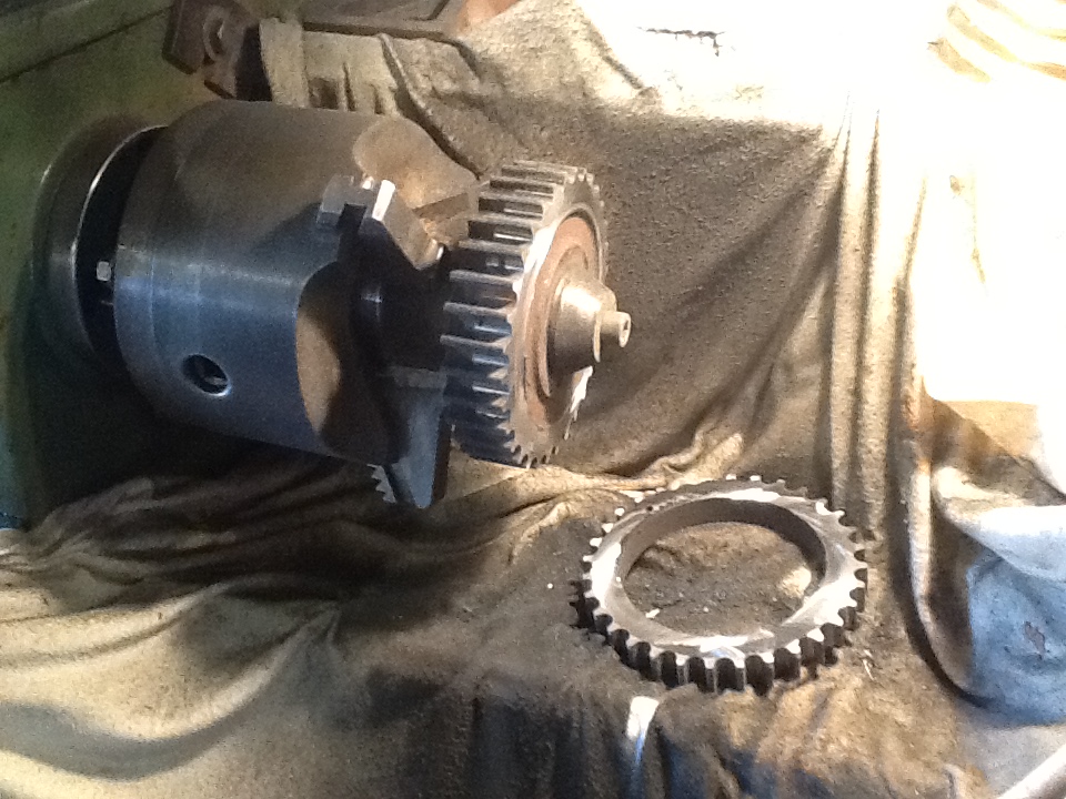
The front side parted off with the disc cutter,
note the wet sack cloth to keep the grit off the lathe bed
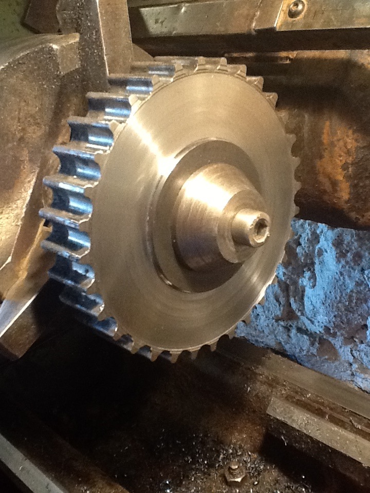
As can be seen from the raised area around the periphery of the job,
the teeth are very hard to cut and
had to be ground off one at a time
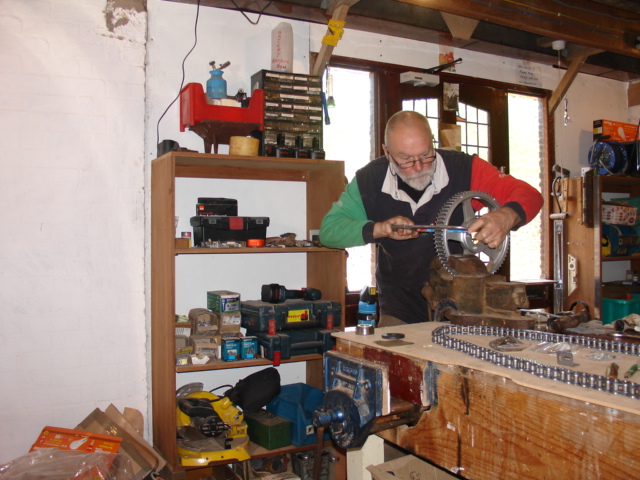
Cutting through the spokes with a hacksaw.
this is just a pose for the camera,
the chain was removed from the bench before it got covered in aluminium filings!
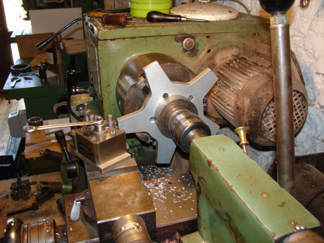
The spokes turned and faced up ready to accept the sprocket.
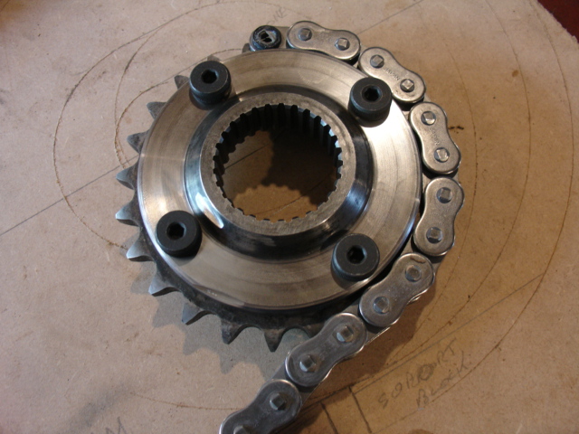
The front carrier with sprocket fitted
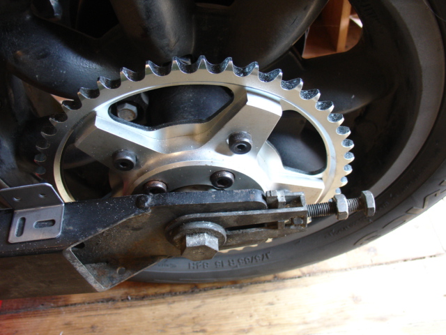
The rear carrier with sprocket fitted
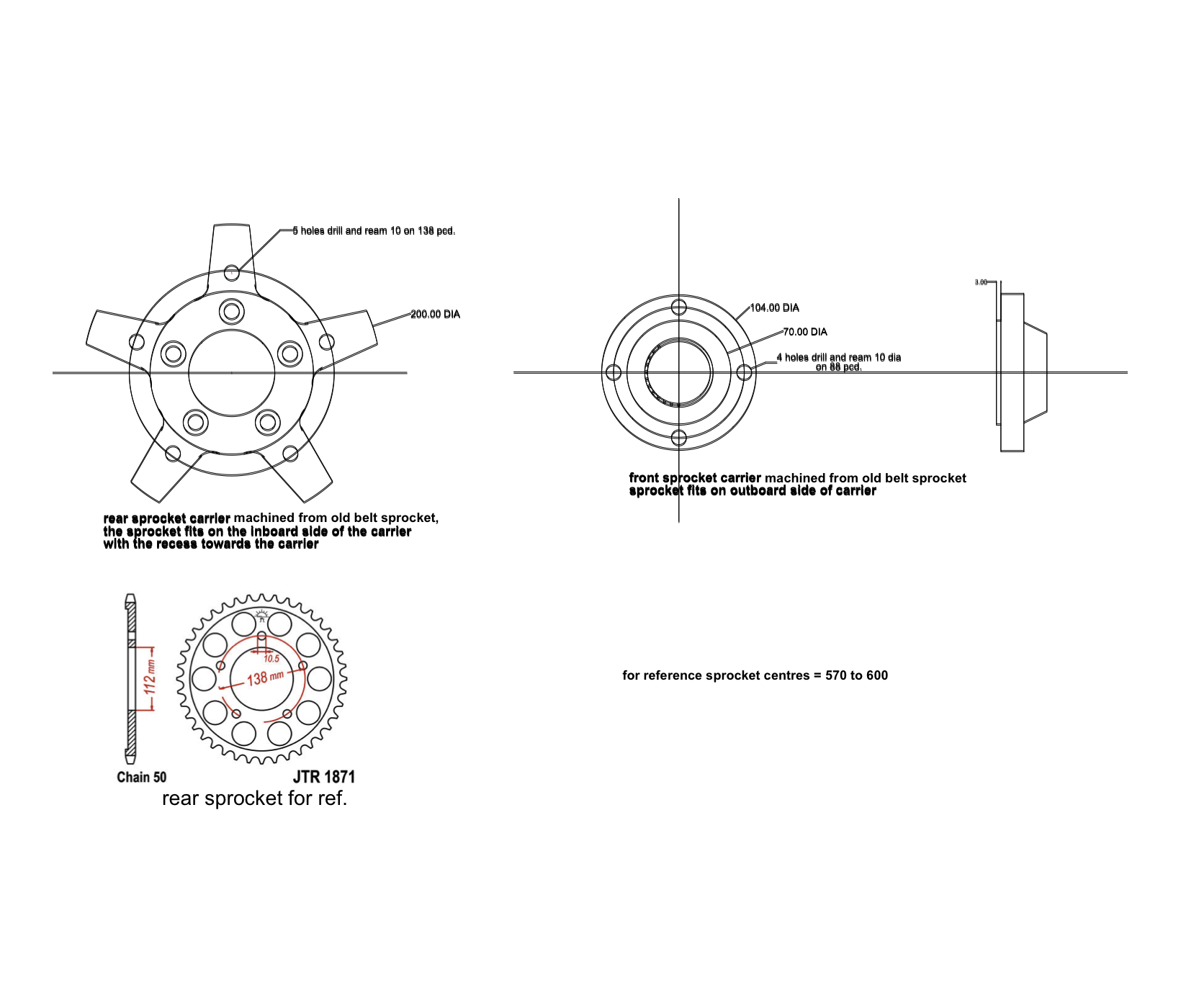
For the DIY owners here are drawings
which used in conjunction with the above text
should guide you through the job.
7/ chain Tsubaki sigma XRS TX4 -Ring steel 116 links.
8/ alignment.
20,000 MILE UPDATE
The chain wheels and chain were fitted at 7,000 miles and now, some 13,000 miles later no obvious signs of deterioration are present. the chain has been lubricated, manually every 500 miles or so with thin machine oil which
penetrates the rollers well. periodically I have cleaned the chain with a high pressure washer. I have kept the chain in good tension - about 10mm. up and down at the middle of the top run with the bottom run taught but have
not had to move the spindle back very much so I think wear is minimal in the chain and the sprocket teeth show no signs of hooking nor do they appear unduly pointed.
BACK TO TOP OF PAGE
9/ the mudguard.
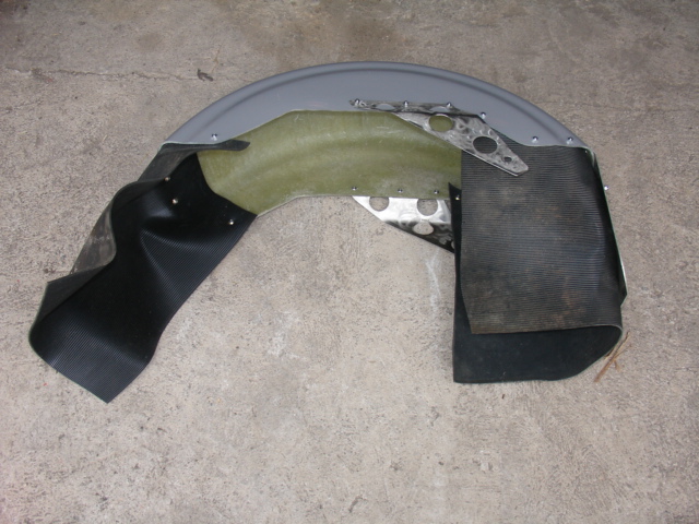
The mudguard prior to fitting with un trimmed mudflaps
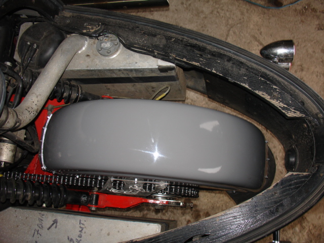
The mudguard in place
10/ first impressions
( August 2017 and just coming up to 16,000miles on the clock, 9,000 of them with the new chain drive and no signs of wear or any need to adjust the tension even after the longest of runs.)
Failure?
Here are a few more general pictures.
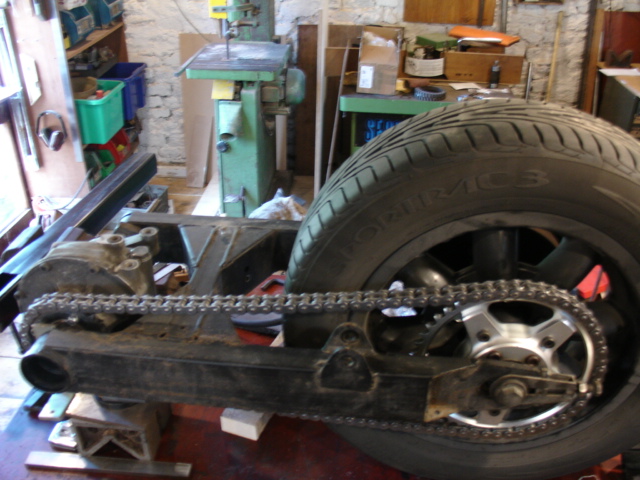
Set up on the bench
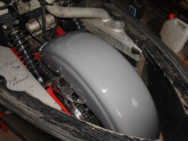
The chain run
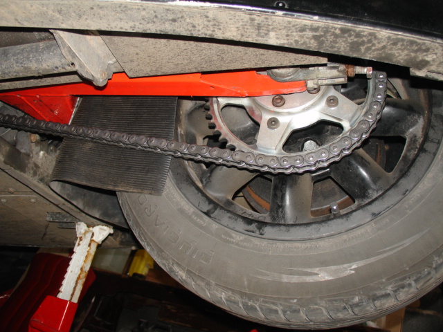
The mud flap keeps the muck off the chain
11/ parts and suppliers
12/ Moving on to the cush drive or compensator.
Having replaced the final drive belt with a chain to good effect but without curing the problem of the banging in the transmission I decided to investigate the Cush drive. My machine is fitted with the Centa designed and built
shock absorber. I believe that the design is based on the Centaflex RS coupling which the manufacturers claim copes with misalignment of the two shafts involved and provides progressive shock absorption by virtue of the four
rubber rollers which provide low stiffness at low speeds. No arguments there, the idea seems sound and works well. It seems that the marine original has been modified to cope with reverse action due to engine braking which is
minimal in the marine environment. The difference is that the cutouts in both inner and outer rotors are now near to being symmetrical which gives cushioning in both directions but on the down side, an increased range of
movement and low stiffness at low speeds. This allows, in my opinion, too much slack at mid range. On removing the engine I found that the starter ring gear can be rotated back and forth 20 degrees total movement just with
finger tip pressure. I believe this to be the source of the abominable clunking if one pulls away in too high a gear or if one is too light on the accelerator for any chosen gear. I have also targeted the Cush drive for the source of
the banging under high acceleration. I theorise that the rollers allow the unit to " wind up" taking up the 20 degrees of slack and also as much as the rollers will allow in compression. If the rear wheel then looses traction, for only
a moment, the Cush drive snaps back to the centre position causing the bang in the transmission. The loss of drive causes the rear wheel to regain its grip and the process starts over.
Quite a theory and it has caused me much work.
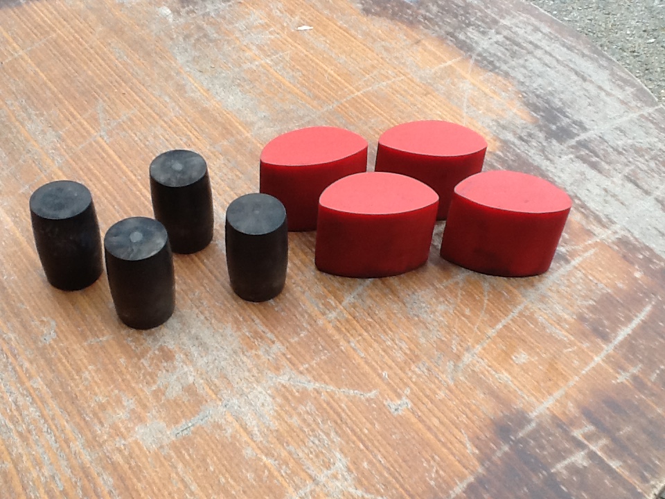
Out with the old and in with the new
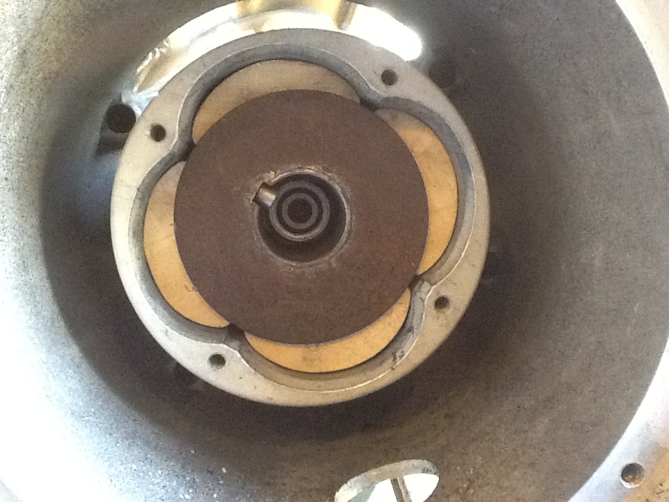
Wooden blocks in place
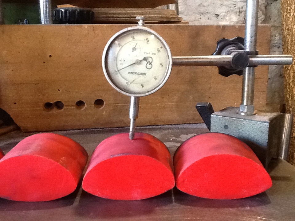
getting the blocks all identical
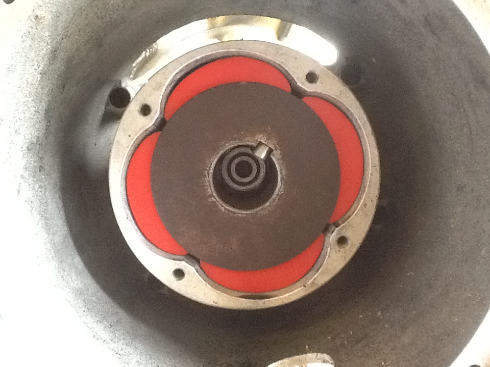
Polyurethane blocks all nicely fitted
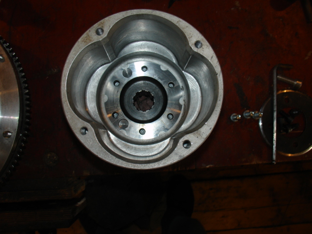
view showing the recess in the outer rotor
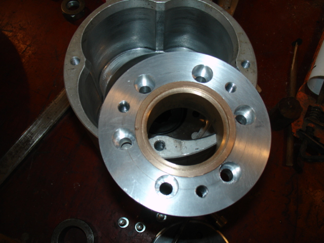
The bush mounted in its carrier, note the O ring groove
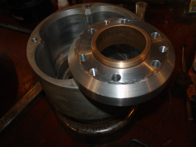
and again, viewed from the rear
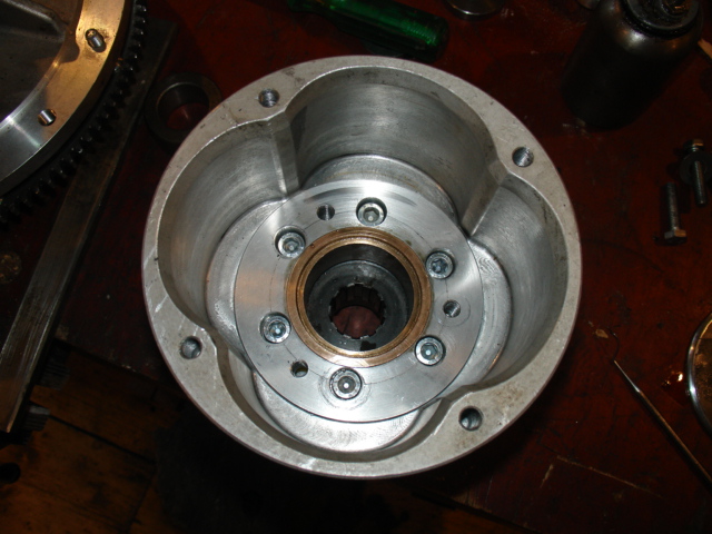
The carrier and bush in situ
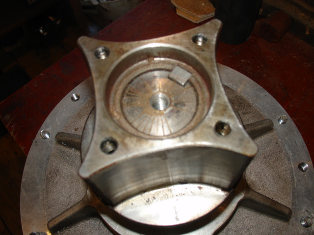
the inner rotor showing the recess for the stub shaft
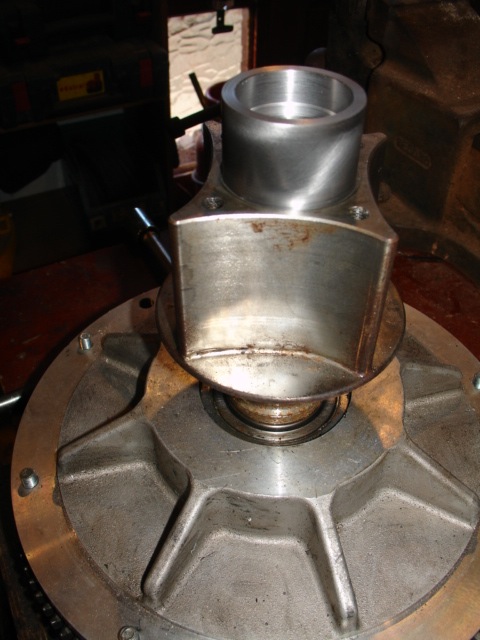
The stub shaft in place
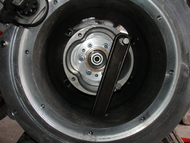
Holding the rotor to tighten the crankshaft nut
can be achieved with help of a big spanner
and a couple of M8 bolts
20,000 MILE UPDATE
Following my mods to the Centa coupling many ups and downs in performance have been experienced and I work, continually towards a more perfect solution. My first run of inserts have proved to be smooth, comfortable and
reliable. The original polyurethane inserts ran, trouble free for nearly10,000 miles and only failed after a particularly hard session at the Curborough sprint circuit when the engine overheated dramatically. Since then I have worked
with modified shapes to give greater strength, modified material specifications to give longer life and I am currently working towards a high temperature material insert which I hope will be the "ultimate" solution. Some noise
has become evident from the Mazda gearbox when running my inserts and I believe that I am near to rectifying this as well - I think the noise comes from bounce in the cush drive causing the input shaft in the gearbox to rattle
back and forth somewhat. A compromise between comfort and soft take up is proving to be very acceptable.
The Centa coupling support bearing has proven to be reliable and trouble free with no issues to report.
The stage 3 mods which allow easy removal and replacement of the inserts have become a must do for anyone who has the engine out for whatever reason. Regardless of whose inserts you chose to fit they must be
seen as a consumable item and having to pay to have the engine out every time they need replacing is ludicrous. the only issue here is why it took me so long to see the answer!
THE TROUBLE WITH CRANKSHAFTS!
The time came when many people wanted the upgraded Centa Cush drive fitted to their vehicles and I was asked by third party installers to make an item which could be fitted by a motor mechanic, off the shelf. Horror was expressed by one potential
installer at the thought of having to do the hand fitting work, so I designed a hub which would fit tightly without hand filing to get the fit right. About 120 people have taken up the offer and for some time it seemed that I had the solution. After about a
year, some owners started to experience noise from the Centa which turned out to be the hub coming loose on the splined crankshaft. In all I have had about a dozen such failures and all have been rectified by fitting an undersized hub - by hand.
An original Centa rotor fitted to a splined crankshaft and back lit to show the minimal amount of contact
( there should be no light showing).
this came from a new 2021 machine pre delivery - zero miles on the clock!
I conclude that the soft material is made undersize where it touches and that it is pulled on to the shaft maybe with an hydraulic puller, deforming the metal to create a fit of sorts. This, of course means that once the fit is disturbed, it will fail because
the tightness is lost due to low elasticity of the metal. Some of my early customers suffered this failure and it is why I developed the alloy steel hub in the first place.
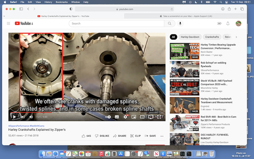
This seems to be a universal problem which may haunt us for some time to come
Worn shafts are recovered by using an undersized hub, hand fitted to the shaft splines - I carry three increments of undersize hub, on the shelf.
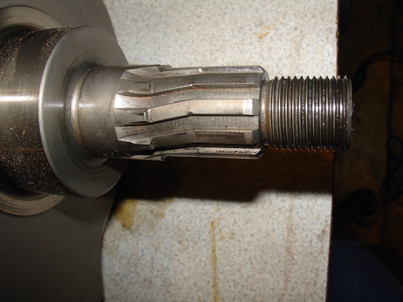
Twisted cranks (above) are usually the result of having had the original Harley style compensator fitted for too long
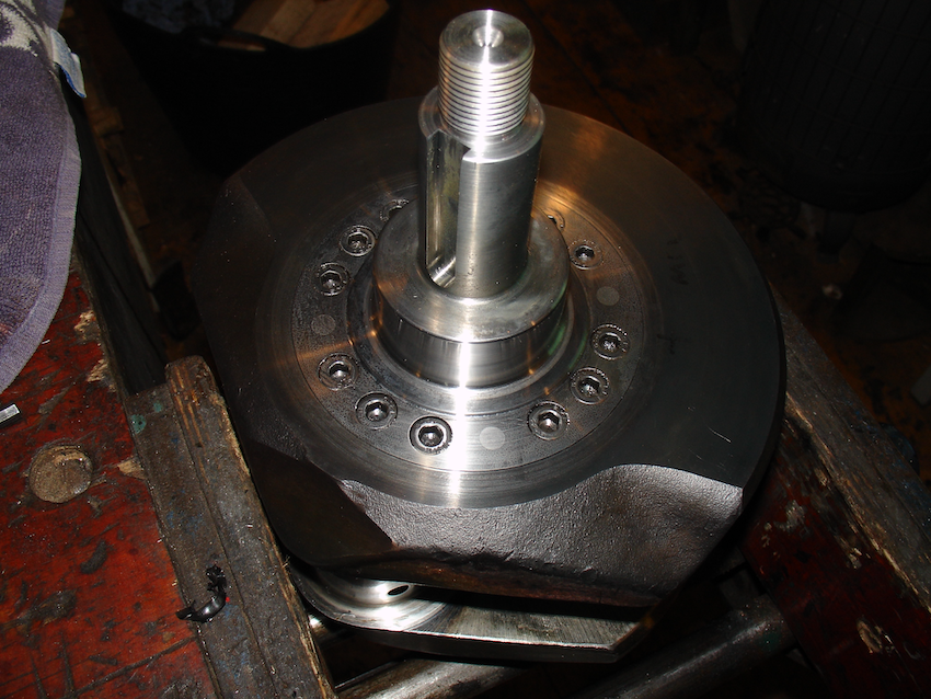
A crankshaft repaired after complete shearing of the drive shaft
BACK TO TOP OF PAGE
Here is a brief recount of my " tour des amis" test run round Europe.
Day one, Lancaster to Ledbury.
I have had this described as " OK for a party trick". Party trick my arse! Every time I go out I have to start my journey with half an hour of heavy traffic round the city - I do not want to pull away at 2,700 rpm plus
every ten yards only to have to dip the clutch before it has fully engaged. What price a new clutch if one keeps that up!
Bit of a rough hill climb up to Richards house and I missed the turn into his drive ending up in a dead end farm track with scant room to turn round but managed it OK.
Day two Ledbury to Exeter
Day three, Exeter to Portsmouth.
Day four, Le Havre to Marcilly.
Day seven Marcilly to Houvin - Houvigneul
Day eight Houvin - Houvigneul to Rotterdam.
Day eleven Hull to Lancaster.
Pleased with a very consistent 35 miles per gallon at every fuel stop regardless of the type of driving.
BACK TO TOP OF PAGE
RE-MOUNTING THE BEVELBOX
Some months and a few miles later I have still to open up the Centa unit for examination, several other factors have crept in to the equation. At the end of November Claire fell off her bicycle and broke her elbow and her
knee which has put everything including three wheeler development on hold. I have, however managed to do a bit of driving which has produced more problems. The loud bang is back and now worse than ever - more
research is called for.
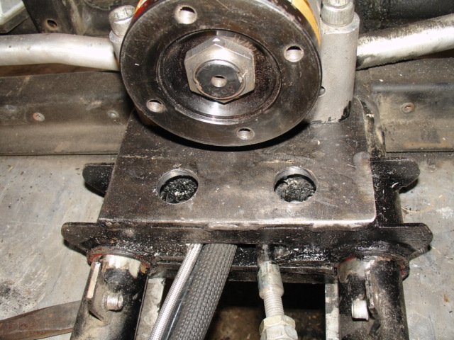
The front mounting clamped to the chassis members
forward of the old mounting position
to avoid the remains of the original mounting bridge
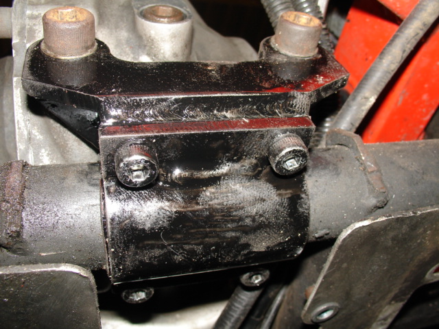
The rear mount clamped to the chassis cross member
between the old welds.
The back of the box being raised clear of the cross member
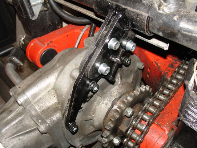
The new top mount in position
cradling the chassis member above and
tightened in place by a jacking screw
20,000 MILE UPDATE
To date, everyone who has fitted my bevel box mounting kit has seen an immediate improvement in smoothness while accelerating, smoother take up from stationary and a marked reduction in vibration.
Bevel box whine however, remains the same. The best reported time for fitting so far is 5 hours.
April 2017 already! I have the engine out and I am pleased to find no signs of wear, tear or damage to my modified Centa drive coupling. The polyurethane inserts are clean, unmarked and there is no sign of dust in
the rotors. When I took the original barrel shaped inserts out there was a good teaspoonful of black dust in the corners. The extended rotor nose bearing is still firmly attached ( I wondered if the new vibrations were
due to it coming loose ) and shows no signs of wear save for a bit of polished surface which I would expect as the bearing ran itself in. The oilite bush is also like new.
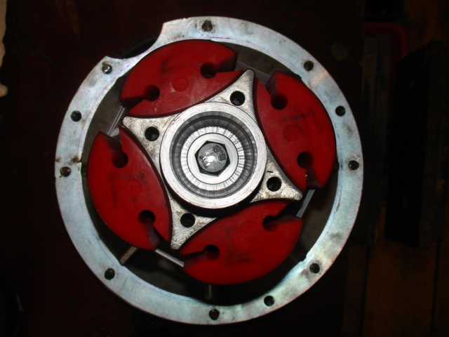
My original inserts showing no signs of wear and now
with "bird beak" cutouts to give a gentler take up.
The journey to a better ride has been long, arduous and full of disappointments and surprises but I am well aware that only serious research and testing leads to success. In the case of an individual such
as me with limited resources and limited knowledge, learning as I go along and applying years of acquired skill and experience in a new field, the ups and downs can be severe.
I started with the "obvious" cause - the toothed belt - I could not have been more wrong. The advantages of converting to chain drive are great but not what I had expected.
My next focus was the Centa coupling - bang on target for the low speed problems and only partly to blame for the high power banging. This in turn showed up the flaws in the "NVH" kit, which
was dumped and replaced - probably the most important modification of the lot. I then came full circle with the vibration showing up in the newly fitted chain drive which pointed me back to the Centa coupling
. A slight addition of freedom of movement here brought me to the end of the journey. Phew! Engine out and in four times - I know how to do that now - several thousand miles of testing, some
enjoyable, some terrifying but all most satisfying.
Many thanks to those who helped me along the way with guidance, criticism, and machines and stories to compare, the task would have been much more difficult without your help.
REPLACING THE CENTA DRIVE HUB
After running my Cush drive upgrade for more than 15,000 miles I began to hear a sort of mechanical rumbling from the drive train and was worried about the cause. Some miles and lots of noise later I decided to have the
engine out to investigate. It turned out to be the splines of the Centa outer rotor being loose on the crankshaft. On removal of the rotor I discovered the crankshaft in good condition but the internal splines of the
Centa coupling were badly worn. On investigation I found the hub of the Centa coupling to be made from soft, probably free machining steel which aids manufacture but is useless as a mating part for the S&S crankshaft.
Further measuring of a new coupling revealed the splines to be a good fit on the driving faces of the splines but to have clearance on both the major and minor diameters; this is usual for a Cush drive such as the Harley Davidson
one originally fitted with its hardened internal splines which have to have sliding motion in order to function but for a softer hub which is static, it is desirable to have a fit on either the major or minor diameters as well.
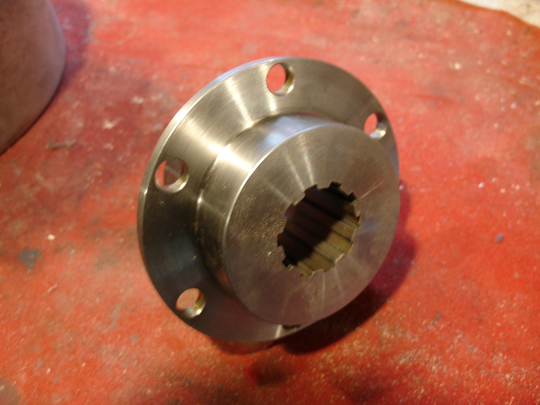
The splined insert for the centa coupling
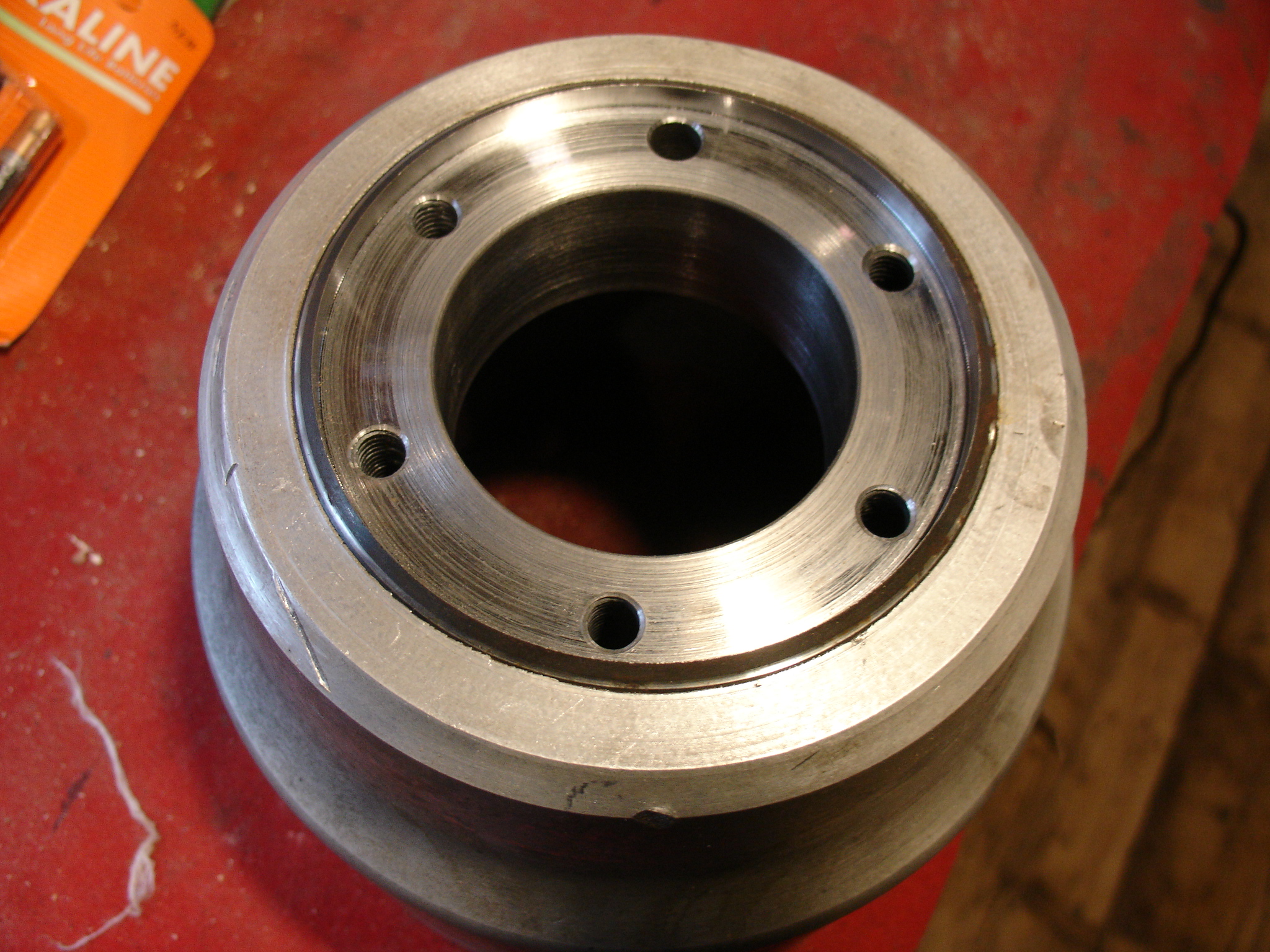
The centa coupling bored out
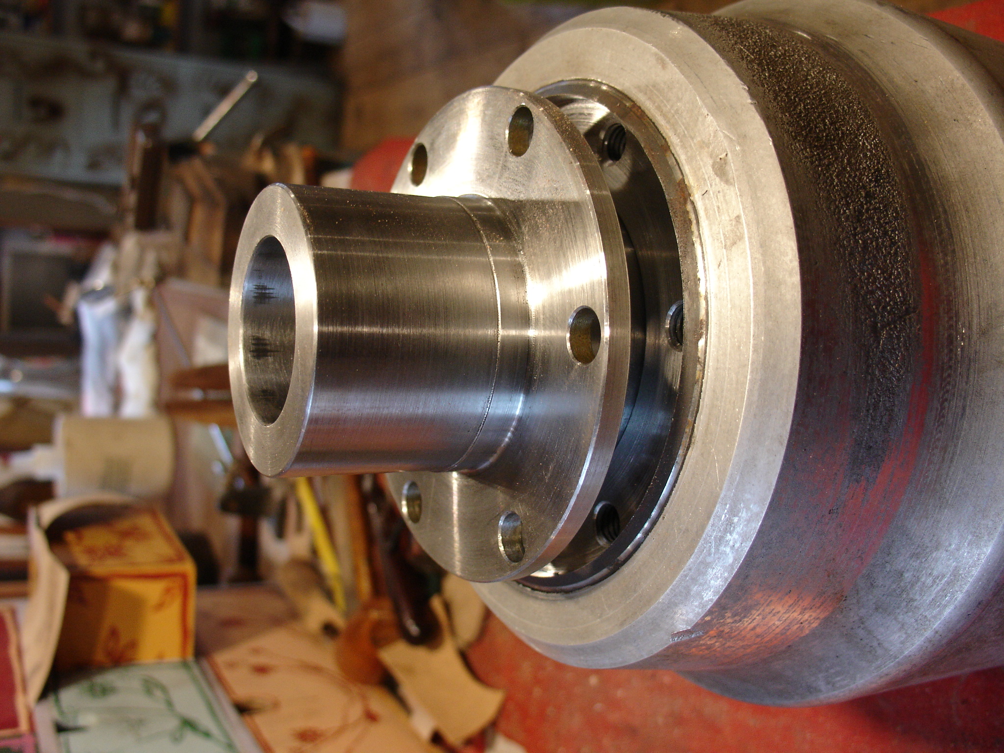
the centa coupling insert half way in
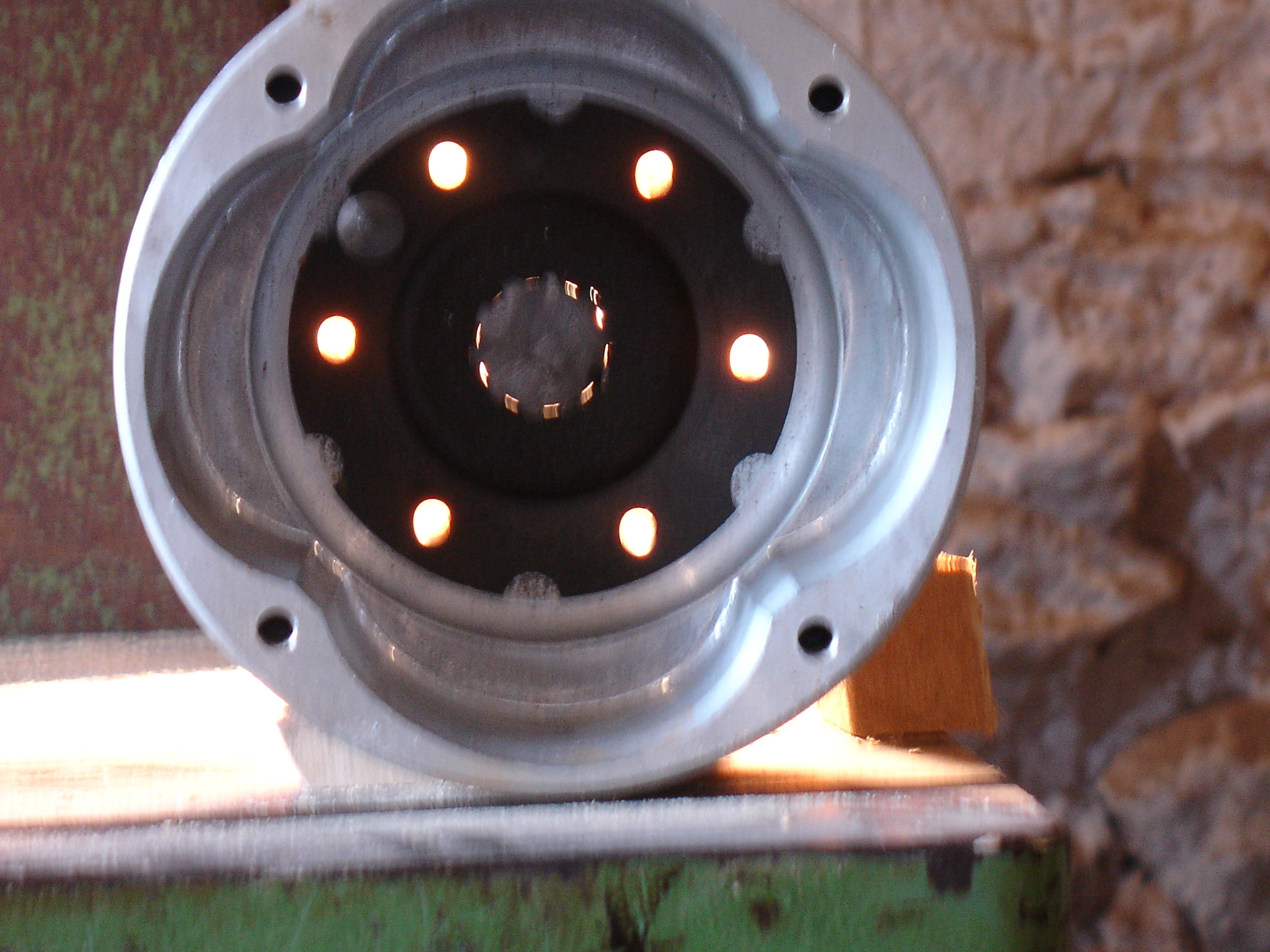
Centa coupling with unworn shaft inserted
showing light where the splines do not fit tightly
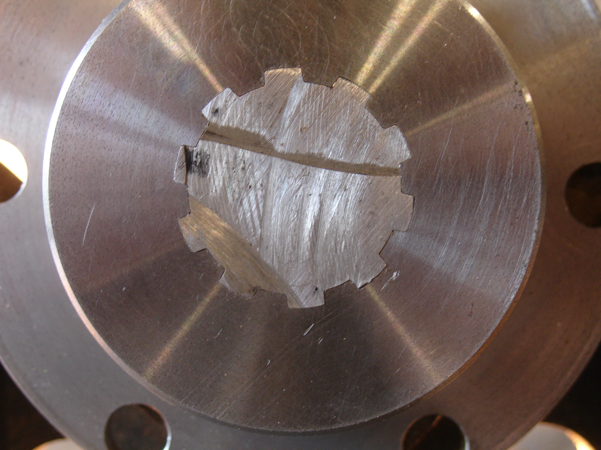
Bleazey insert with unworn shaft inserted
THE QUICK CHANGE MODS. - a light bulb moment!
January 2018 and I am driving to the new year dinner party with the Lakes and Lancs. centre of the Morgan three wheeler club. I am in the Landrovardo as snow is still lying on some roads and more is forecast. Poodleing along
the motorway gives me time to reflect on what I have been doing in the way of research and to the huge waste of time and effort every time I remove the engine to do a simple change of the Centa inserts. Why, I ask myself is this
so difficult? this coupling has origins in the marine world. If you loose drive at sea, in bad weather conditions you need to get it back again pretty quick or the situation becomes life threatening in very short order, why would
Centa, a reputable maker of marine couplings allow this? Obviously they do not - then the light bulb goes on - Morgan have fitted the inner rotor of the Centa coupling the wrong way round (which does not allow a quick change)
and why should they not? they probably had no inkling of the longevity of the inserts in this novel application.
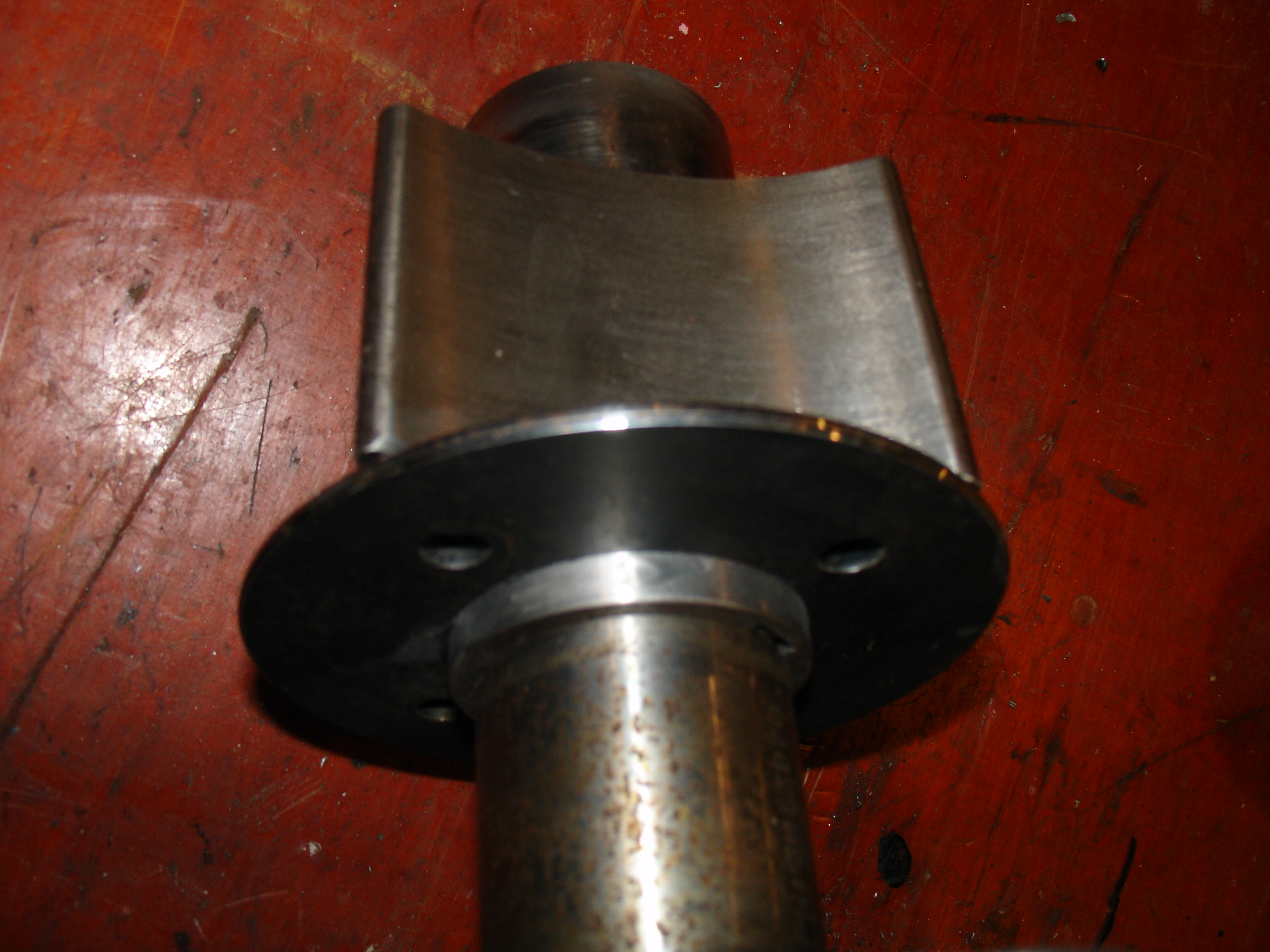
The re machined inner rotor
with the retaining plate in it's new position.
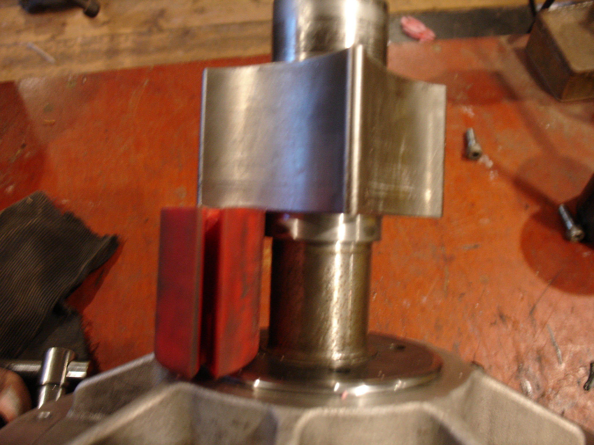
The inner rotor with
the retaining plate pulled back
and an insert in place to show the space restriction
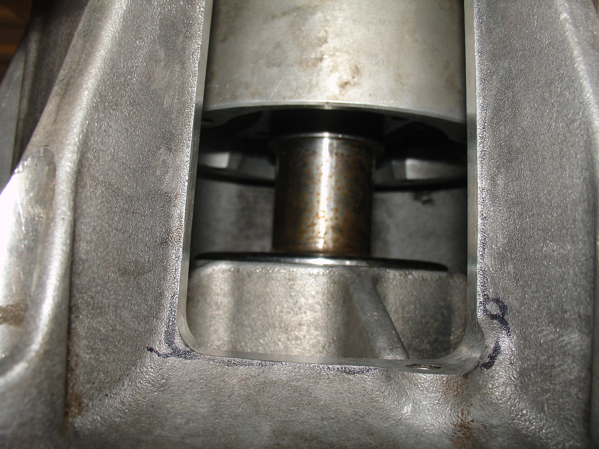
the underside of the bell housing
showing the cut out
MY ENGINE REMOVAL PROCEDURE
Having removed the engine a couple of times I thought it would be a good oportunity to write a guide for others who might want to take on the job. Some months later, having had the engine out six times I have added a few preferred techniques.
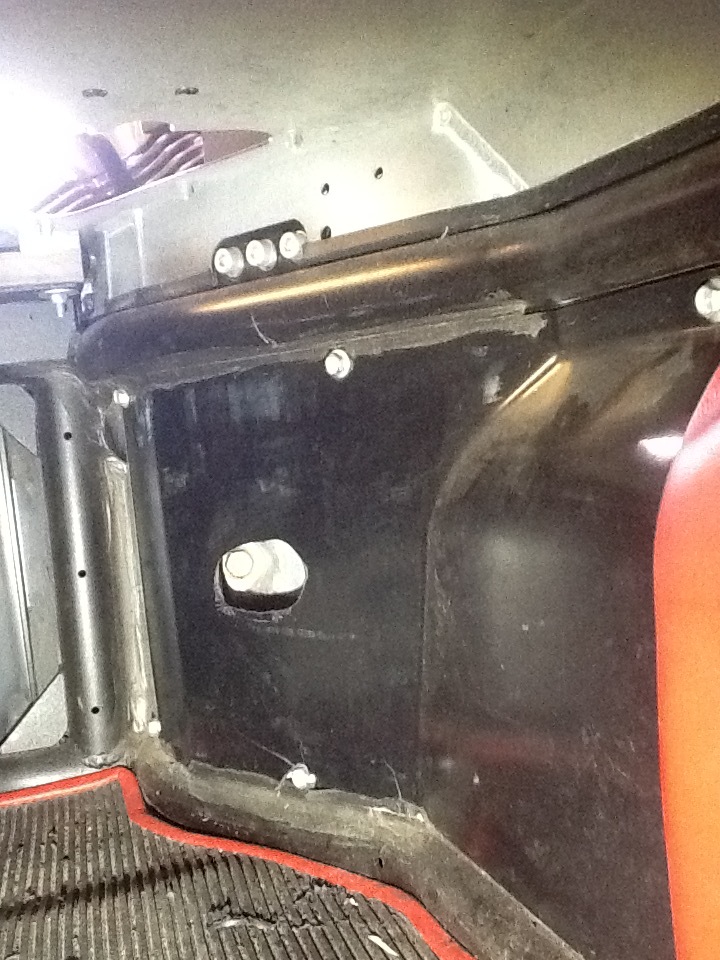
drill here with a30mm hole saw
to get the spanner on the bell housing bolts,
you need two holes on the right side.
this is not necessary, see update
THE LUGGAGE RACK
I wanted to carry luggage on my 5 speeder but did not like the look of the factory supplied rack, most especially the suction cup idea. I don't know why but it just does not seem to go with the machine.
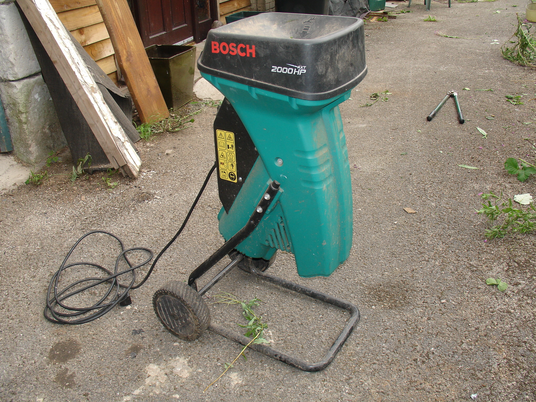
The Donor Shredder by Bosch
You will see that the supporting frame of the shredder is tubular steel and given a closer look the components for my luggage rack began to appear. An hour or two with hacksaw and welder gave me the frame.
Add a short length of 25 x 25 box section and some 2mm plate cut to form the clamps and forks and I was in business
I chose to mount the whole affair on the roll over bars. A quickly removable bolt holds the clamps in place at the top of the hoops and the bottom forks just rest against the tubes, the weight of the load holding
it all down. I do not have any trouble with it lifting as I drive over bumps. The forks and clamps are lined with leather so as not to scratch the chrome.
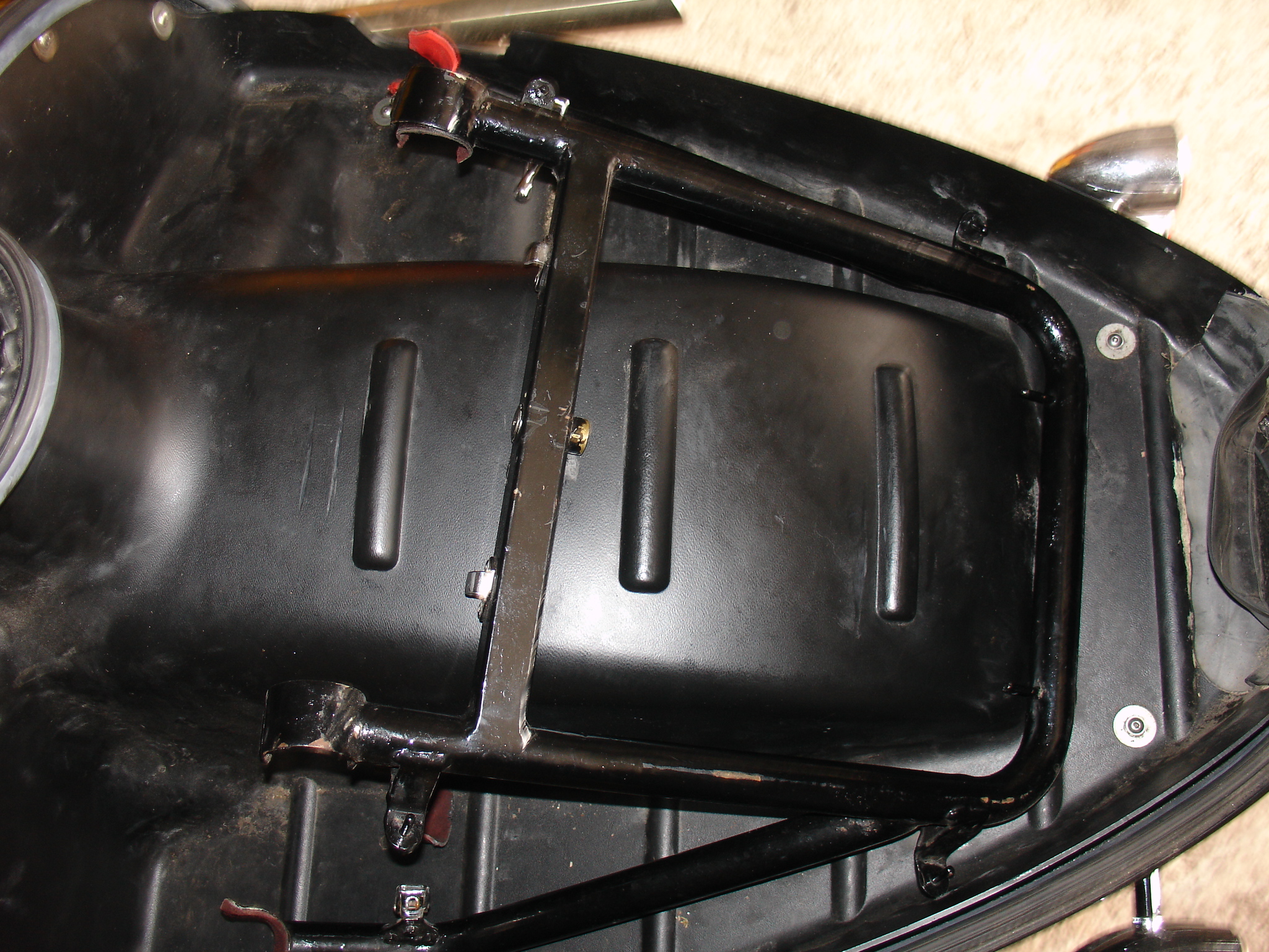
Snugly Packed Away
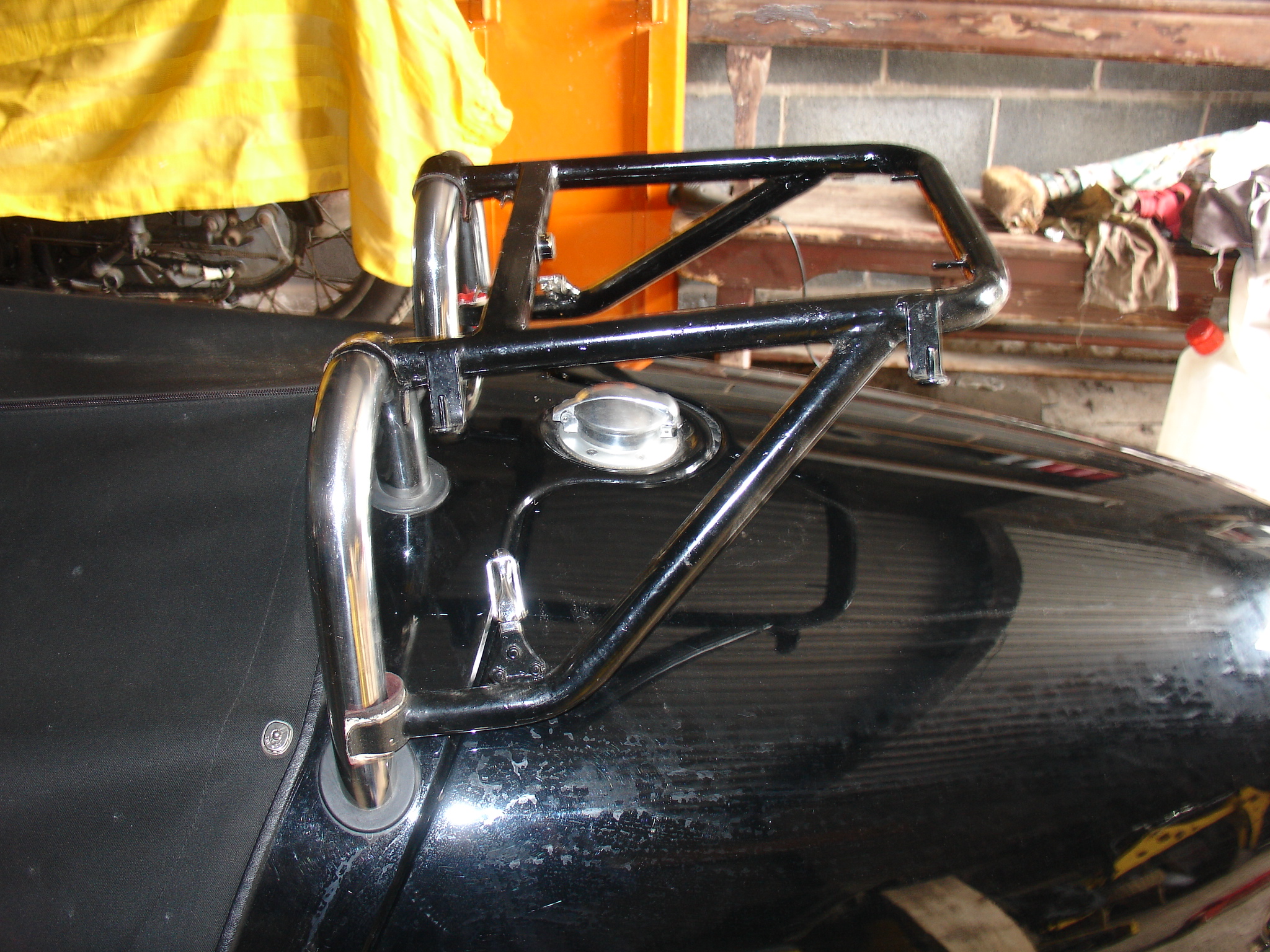
The bare rack is useful for carrying other things
I used Craven's rubber fittings for the top of the panniers and the back of the top box with
some nice chrome toggle clamps, found on E-bay, to hold them all securely in place. An old steering lock from a Triumph motorcycle prevents the top box being stolen and while that is in position the
panniers can not be lifted off.
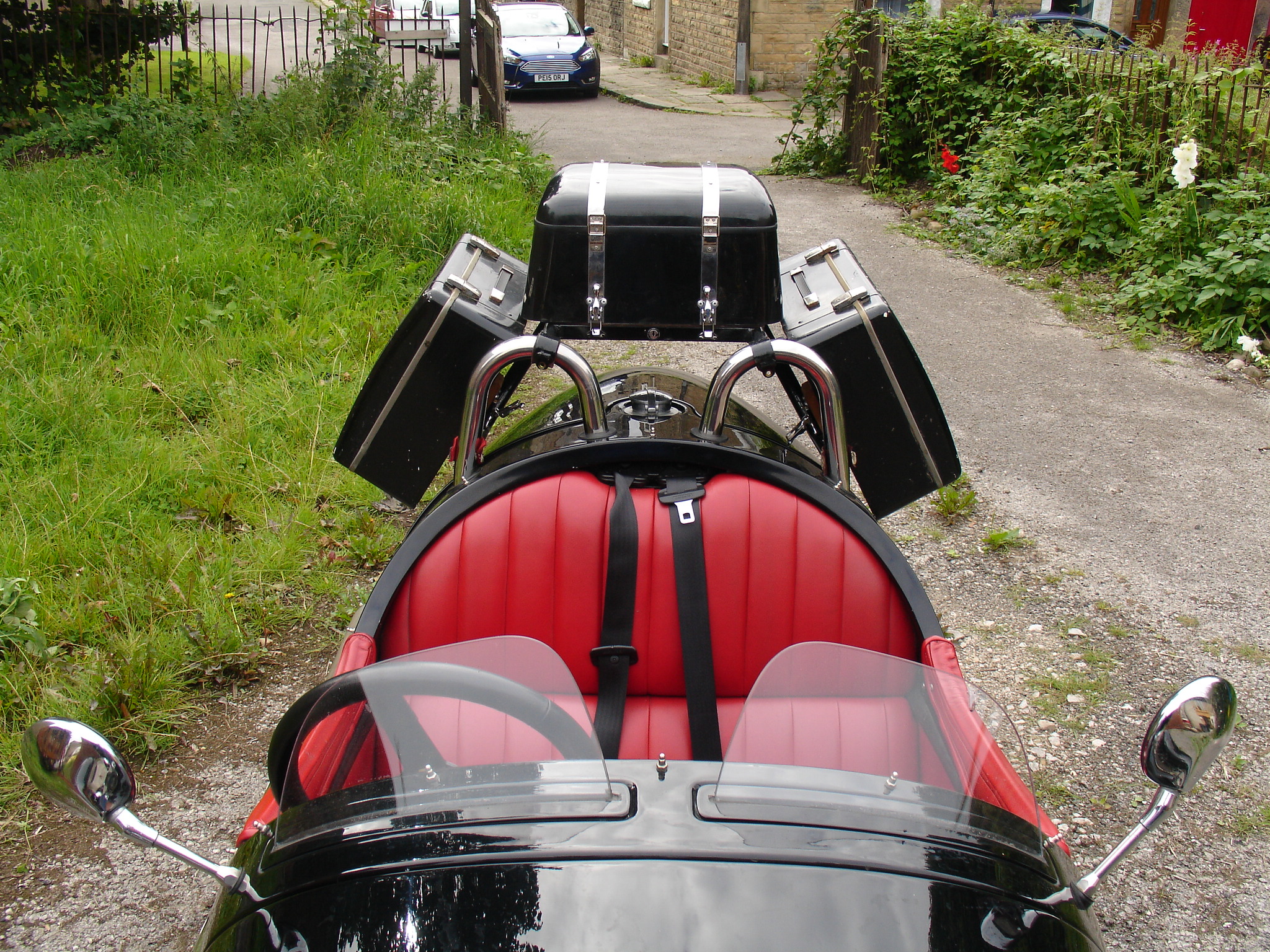
I think it all looks OK
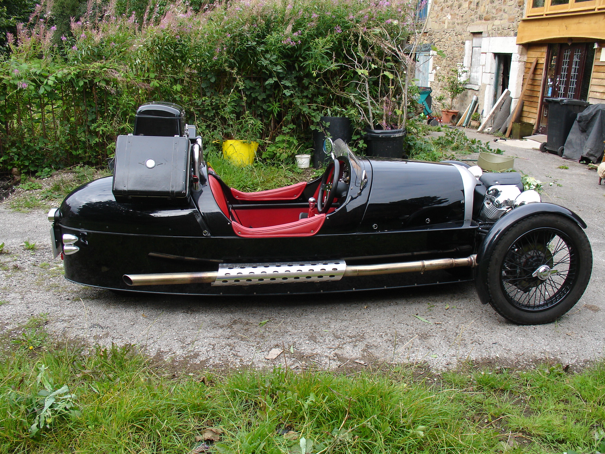
Side View
I do have to remove the top box to make filling with petrol easier but with care it can be done with everything in place. Not letting those last few drops from the nozzle go down
Claire's neck is quite important!
BACK TO TOP OF PAGE
THE STEERING RACK:-
The steering rack on my machine started to get very stiff last winter. Stiff enough to overcome the castor action on the way home one afternoon. I had parked outside a relatives house for three days over Christmas, in torrential
rain and the steering rack had filled with water! The cure involved stripping out the rack to remove a fine coating of rust where the bushings run at the ends. Not something I want to do every time I go out in the rain.
20,000 MILE UPDATE
No further problems have been encountered even though I use and sometimes park the vehicle in the rain.
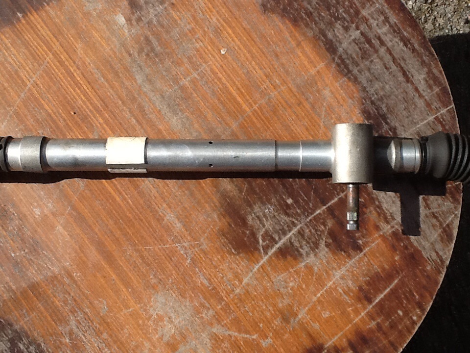
The steering rack showing both holes
BACK TO TOP OF PAGE
THE STEERING ROD ENDS:-
The rose joints on the end of the steering rods need to be lubricated and they come with non return ball valve lube points. Finding something which will get oil or grease in through these things is a challenge and so I have drilled
the rod ends, on top, to accept conventional grease nipples. Surprisingly enough, when I removed the rose joints I found no trace of lubricant at all inside them, I am obviously not the only one who has the problem - even the
dealer didn't get anything in there when it was serviced.
THE BONNET CATCHES:-
The bonnet catches.
The machine comes fitted with Dzus fasteners which, correctly applied, are a gem. They are unobtrusive, easy to use, don't rattle and I guess, would pass the Single Vehicle Approval requirements. They are designed with their
little wire spring to hold hinged panels shut or panels which lift off completely. They do not work on panels which slide open, to make them work on sliding panels they have to be mounted on a little hinged plate. The Morgan
bonnet is a sliding panel, as far as the fasteners are concerned, ie. the panel slides upwards to remove it. The boot lid is the same and the problem has been addressed by fitting little hinged plates, in the form of a leather strap
( which brings its own problems with damaged paintwork and stretching of the leather ).
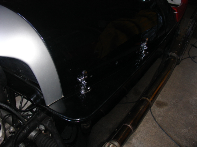
The rear catches are fastened down to the body with M5 stainless button heads screwed in to the ash frame, I drilled a 4mm hole in the wood and just screwed them in - sort of self tapping. the screws are 20mm long so they
should hold well enough.
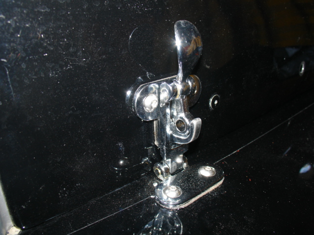
A similar solution for the boot closure eludes me at the moment but I am sure one is out there somewhere.
THE EXHAUST PIPE AND RECTIFIER MOUNTS:-
Whilst cruising down a quiet country village road in France on my recent trial run I was startled by a clattering from the road beside me only to see the right exhaust pipe dragging along the tarmac. I grabbed the thing up and
coasted to a stop in a farm gateway, wired it back in place and continued on my way.
Rectifier mounting revisited.
20,000 MILE UPDATE
The rectifier remains bolted to the bodywork at the passengers feet and has not been disturbed nor given any trouble since it was moved at about 10,000 miles.
the exhaust pipe rubber mounts have continued to fail although not so often. I have a set of heavy duty hexagonal ones in place at the moment but only time will tell if they are up to the job. Recent reports show
a Renault 25 exhaust bobbin is by far the best and this is what I am now using - find them on E-bay
In the mean time I have fitted leather straps from the screw at the back of the leather trim on the body side arm rest to the rear heat shield mounting which catches the pipe and prevents damage in case of failure.
I will be happy when I find a solution which will mean I can remve the straps again!
BACK TO TOP OF PAGE
THE PEDAL BOX:-
"Plenty of people taller than you drive one" said the slick looking sales guy at the factory; I just nodded and said "hmmm". In my mind I was logging the first of the mods which I would undertake on this "project purchase".
I challenge anyone taller than me to sit behind the wheel of this machine with knees up under the rim of the wheel and left foot held back from riding the clutch, for six hours and still be able to walk!
THE TIMING BELT COVER:-
Thanks to members of Talk Morgan for pointing me towards this one. It would seem that heat is detrimental to the longevity of the timing belt so S&S have introduced slotted timing covers and spacers behind the fixing bolts to
allow some air circulation.
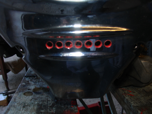
I thought that a long cut edge through the chrome plating might be asking for trouble so I have drilled a row of holes which might do less to undermine the plating and I introduced some 2.5 mm.
thick brass washers between the mating faces. Time will tell!20,000 MILE UPDATE
No changes here and so far no sign of belt deterioration.
BACK TO TOP OF PAGE
PROP SHAFT GREASING:-
Nearly all applications for this type of prop shaft set up involve an offset between diff and gearbox flanges - sometimes two with intermediate bearing support. When it comes to greasing the hardy spicer units
( it is worth researching how to do this as a complete purge is recommended ) one has to revolve the shaft, till the grease nipple comes to the more open side of the joint, in order to get a grease gun on it. The M3W set up involves
little or no offset and so there is no possibility of getting a grease gun on to the nipples and I can not find a slimline version which would make it possible. So what do the dealers do at service time? I'll bet they don't remove the
propshaft from the machine in order to open up one side of the coupling and get some grease in. I will purchase some long series nipples for mine and change them over next time I do the job. This will introduce a bit of
imbalance but I think the risk is worth it.
I am also tempted to ask why a sliding spline and two hardy spicer joints are required in a system which does not involve movement up and down at one end? A couple of rubber doughnuts like the ones fitted to BMW cars would
have been more sensible from a point of view of their shock absorbing qualities and being maintenance free.
POWDER COATING
The headlamp mounting brackets started to shed their powder coating when they were a couple of years old. I touched them up with paint. Later I noticed areas of coating bubbling up on the mudguards
as well, these proved to be more serious and while fitting new tyres I decided to patch them up as well. Patching up was not a sufficient remedy!
It seems bizarre that a wheel secured with a quick action knock off nut will not come off without removing the mudguard as well but I guess fitting the guard that close has a payoff in appearance.
Large areas of powder coating were easily scratched of with a thumbnail and a rotary wire brush shifted much more. I have decided to give them a proper coach paint finish instead. I have left the
intact powder coat in place - if the wire brush won't shift it it should be a good base for my paint. I have opted to use a paint available only in France from a company called Avi.
Their anti rust paint, Avi fer, for iron and steel has worked well on the Velocette in the past.
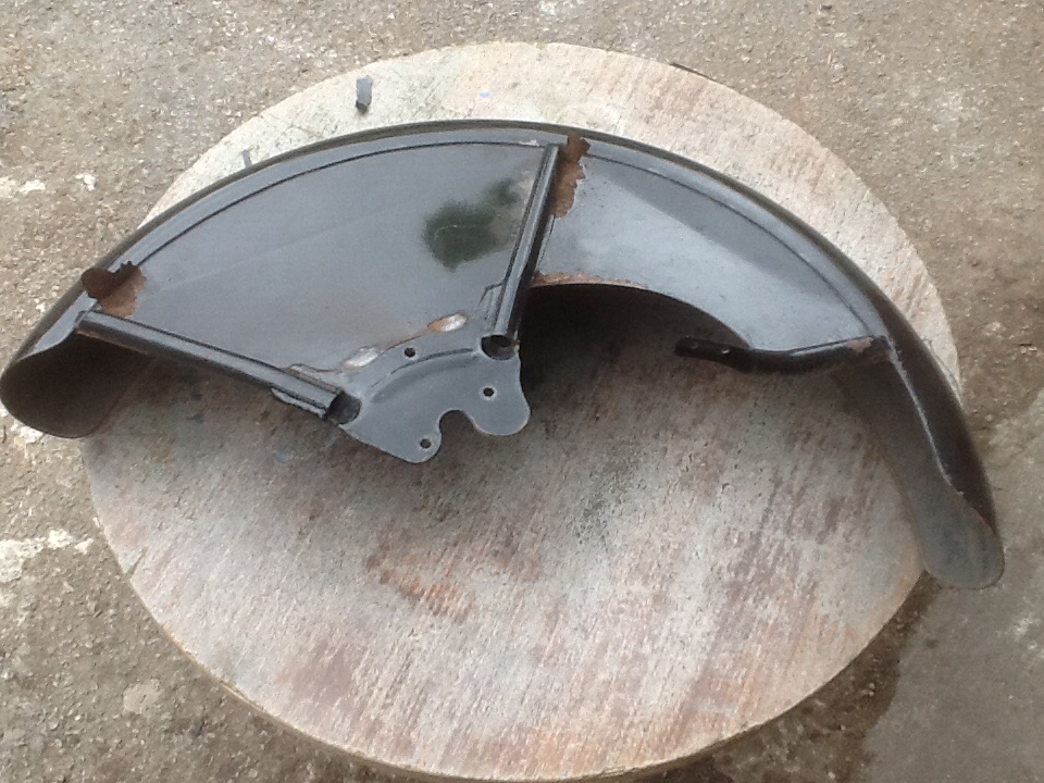
Front mudguard with salt induced rust
showing under the powder coating
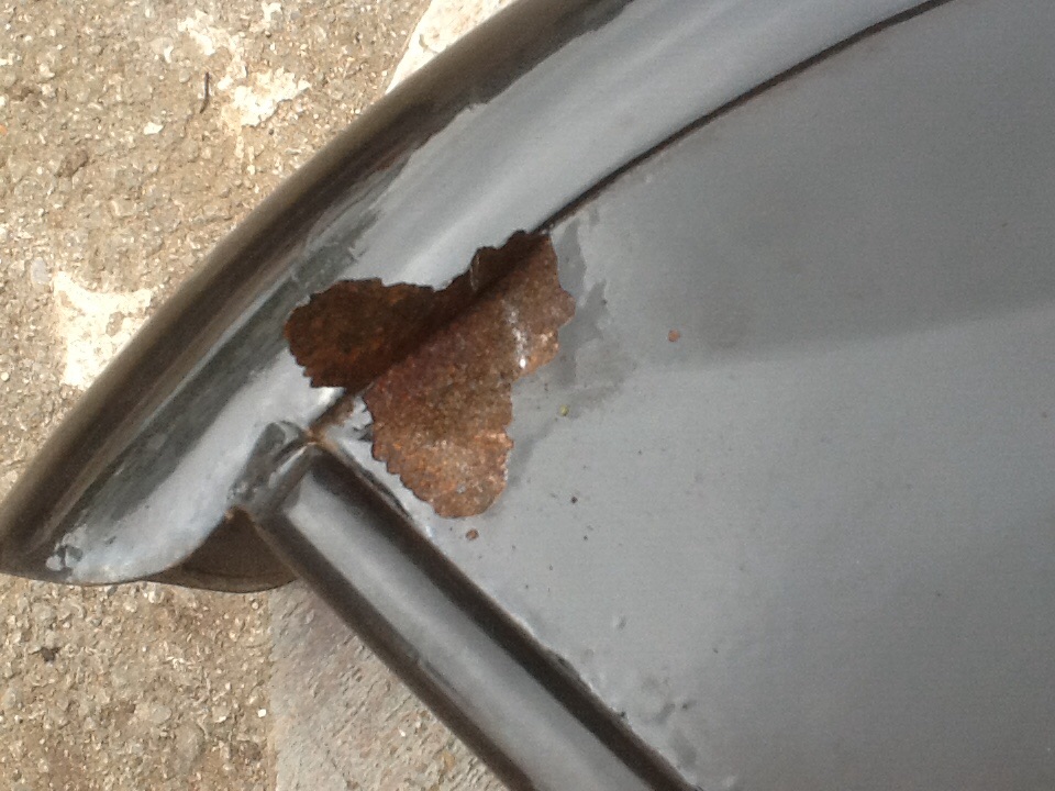
A section of powder coating
peeled back with my thumb nail
showing the rust formed underneath
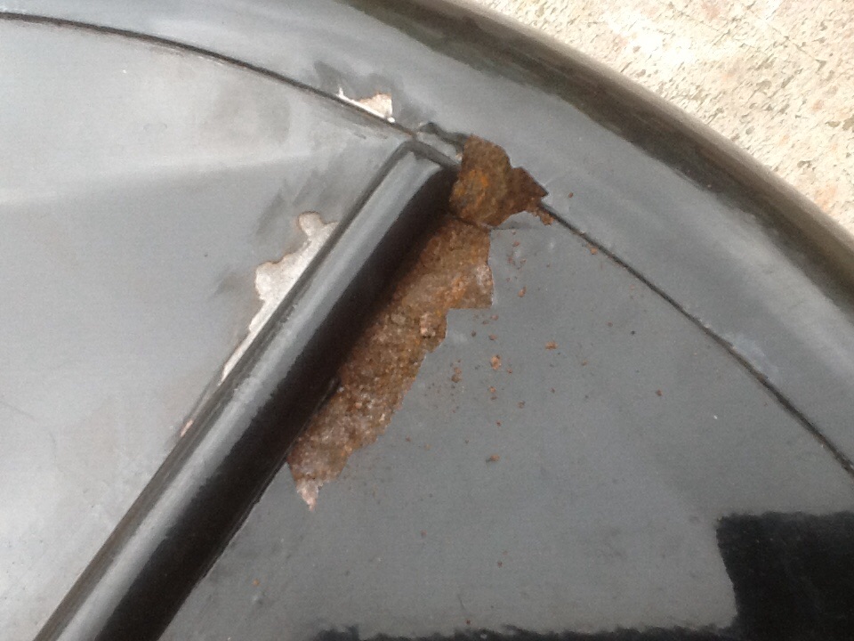
The powder coating peels back with thumb nail pressure
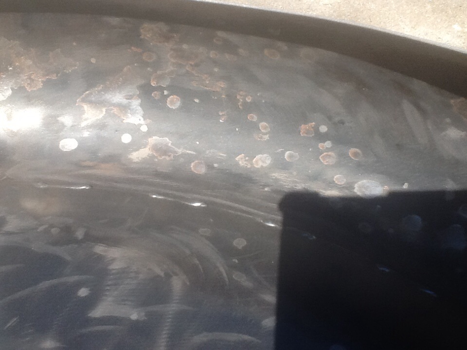
A light brush over the inside reveals many
more patches of rust
Some observations on powder coating.
These are generally answers from the Internet to questions I have about the failure of powder coating on the front mudguards and headlamp mounting brackets on my Morgan threewheeler.20,000 MILE UPDATE
Since repainting the mudguards I have noticed some further corrosion in the same places which may be down to using a rotary wire brush to remove the original rust. I have learned theta this can smooth over the surface leaving some rust under the polished top layer. I will rectify this by re preparing the spots using abrasives and repaint. there are no areas of powder coating which have not failed to some degree and all of it will eventually have been replaced with paint.
BACK TO TOP OF PAGE
INNER TUBE DAMAGE
On replacing the worn Avon front tyres which, made 10,000 miles before they needed replacement, I noted some small cuts in the inner tubes. These cuts were nearly all the way through in places
and coincided with every other spoke nipple, all of them, on both wheels. The spokes which go to the inboard side of the hub were the ones at fault. You will see, from the photo below, that the
moulding line on the tube is distorted in a wavy pattern with no damage in the waves adjacent to the damage. On speaking to both Blockley who made my inner tubes and also to MWS int.
who made the wheels I was told that the bead of the tyre should cover the nipples sufficiently to protect the tube. To see what was going on I cut a 200 mm long section out of one of the old Avons and
fitted it in place. I saw that about 25% of the nipples remains exposed and this is very obviously the cause of the damage. Searching for an answer I found no available rim tape other than the self
adhesive form and much advice to use duct tape. This is all very good in the well of the rim but MWSint. Advise that introducing anything under the bead which will increase the circumference
of the rim is likely to over stress the bead and cause failure. My answer, in the light of no other, has been to use a polyurethane mastic/ adhesive which covers just the exposed part of the nipples,
does not get under the bead and dries to a hard sandable, paintable surface. If you have to move the nipples to re true a wheel it comes off OK with a rotary wire brush. It will be interesting,
When the Blockleys are worn out , to section one of those and see if the nipples are covered by the beads on those tyres.
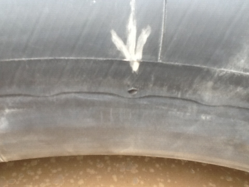
One of the cuts in the tube -
they are at 70 mm intervals all the way round.
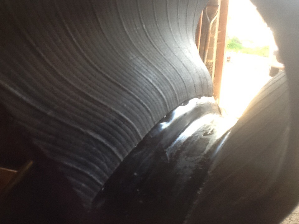
An internal view showing the exposed spoke nipples which cut in to the inner tubes.
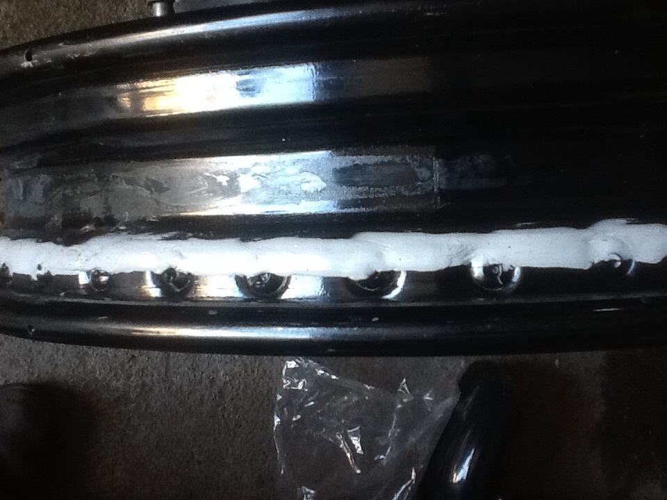
The spoke nipples coated with " marine mastic" to prevent contact with the inner tube.
20,000 MILE UPDATE
The Blockley tyres which I fitted at 10,000 miles have been replaced after a similar mileage and I think they would have made 11,000 if I had not replaced them a little prematurely due to this years impending trip to France.
The marine mastic used over the heads of the spoke nipples has remained intact and gives no cause for concern. The inner tubes, on inspection have no damage whatsoever.
BACK TO TOP OF PAGE
CHASSIS CRACKS
Several people have recently discovered cracks in the vertical chassis member where the rear mounting of the forward arm of the lower wishbone meets the chassis. I believe that the factory have offered to rectify this free of charge and are busy designing a new mounting. If you are able to transport the vehicle to the factory or wherever
they choose to carry out the work then I recommend this as the best option.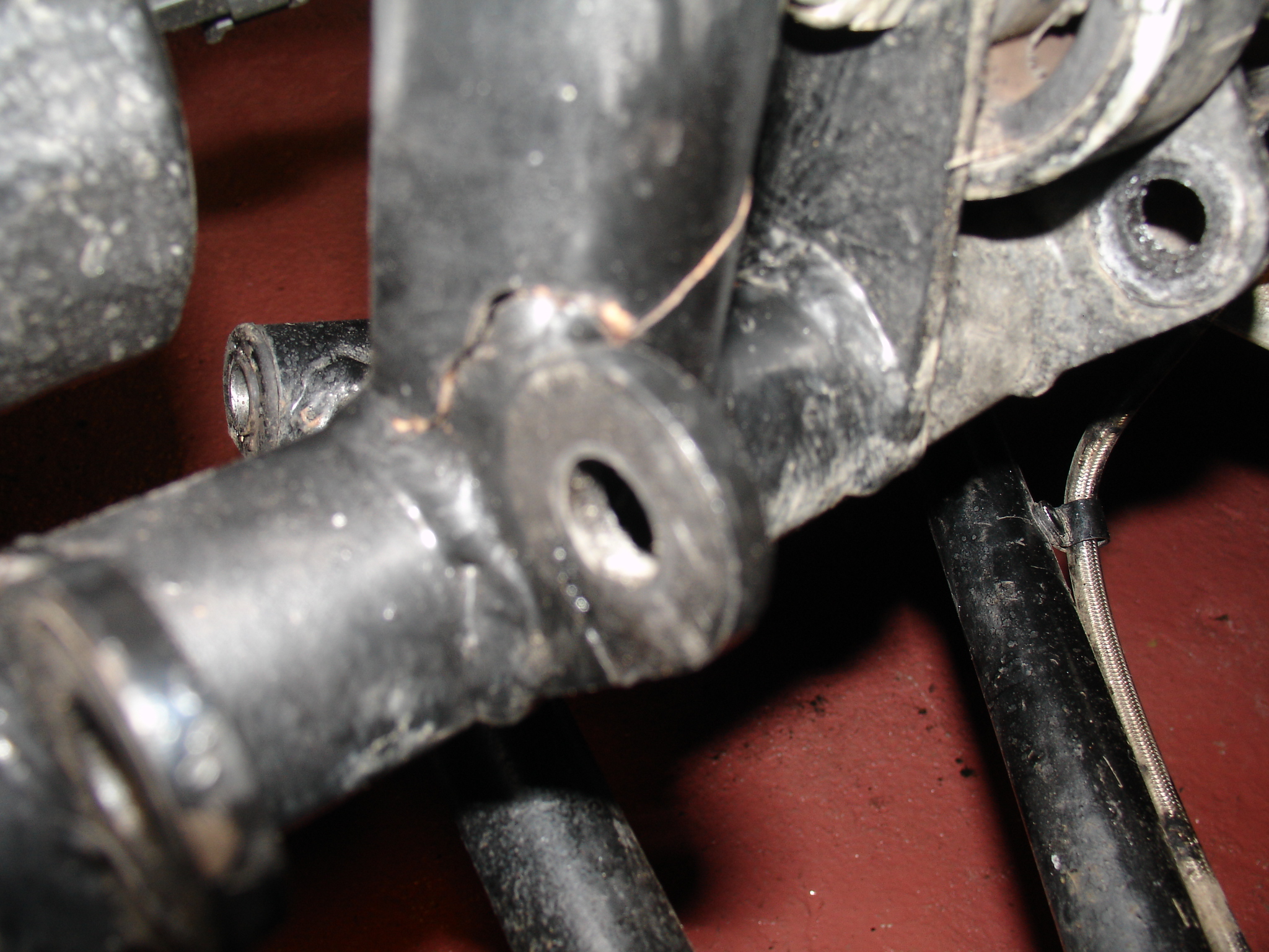
THE CRACK AS FIRST DISCOVERED
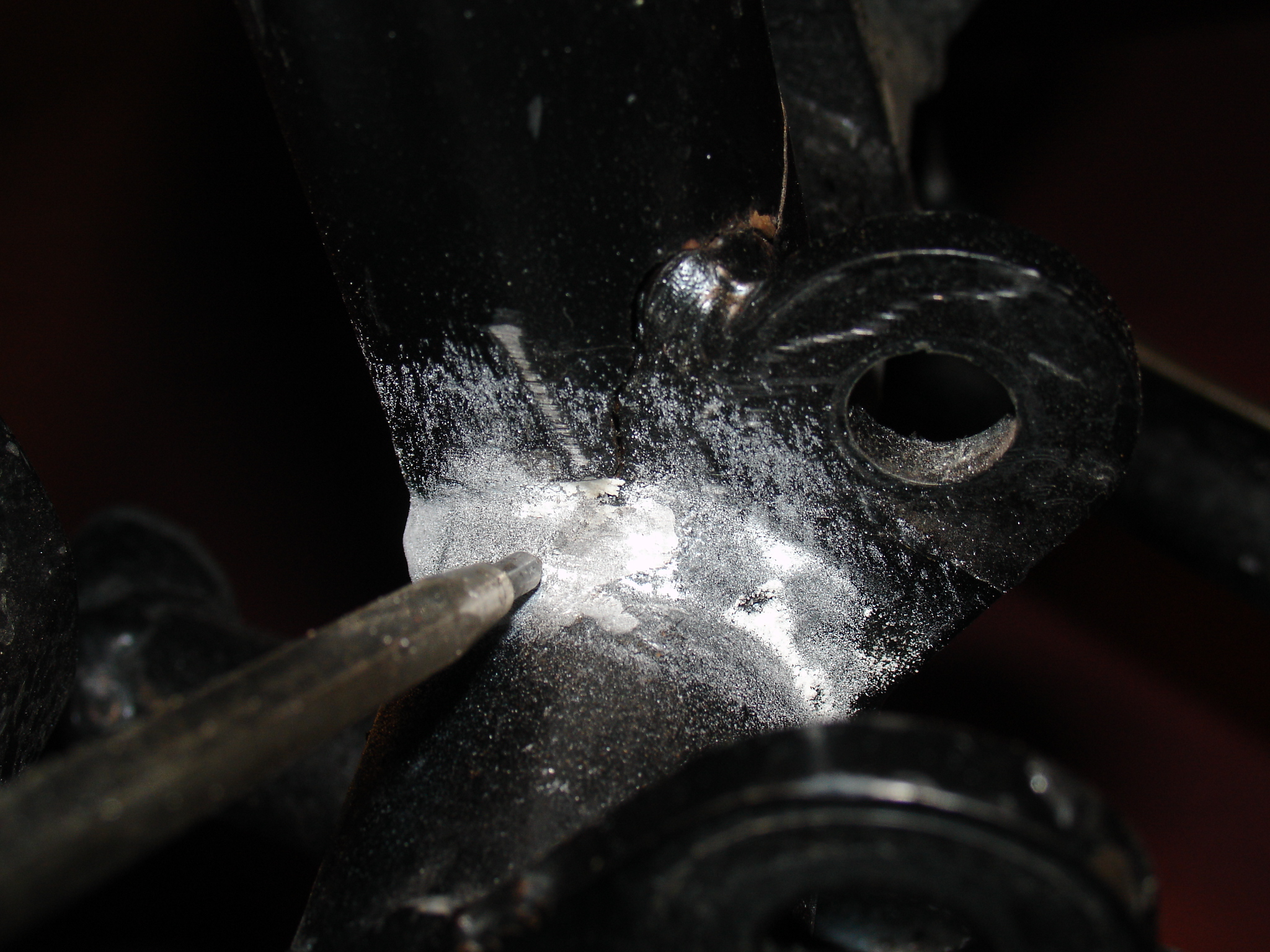
THE POINTER SHOWS THE EXTENT OF THE CRACK AFTER DETECTION USING PENETRATING OIL AND FRENCH CHALK
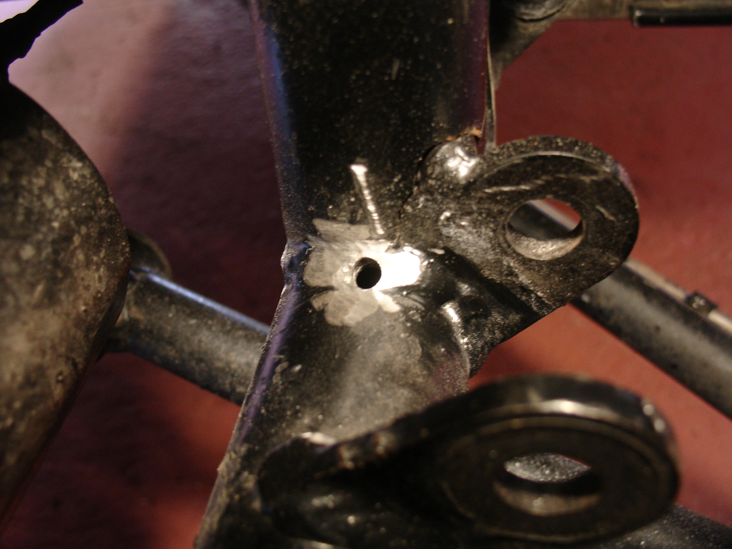
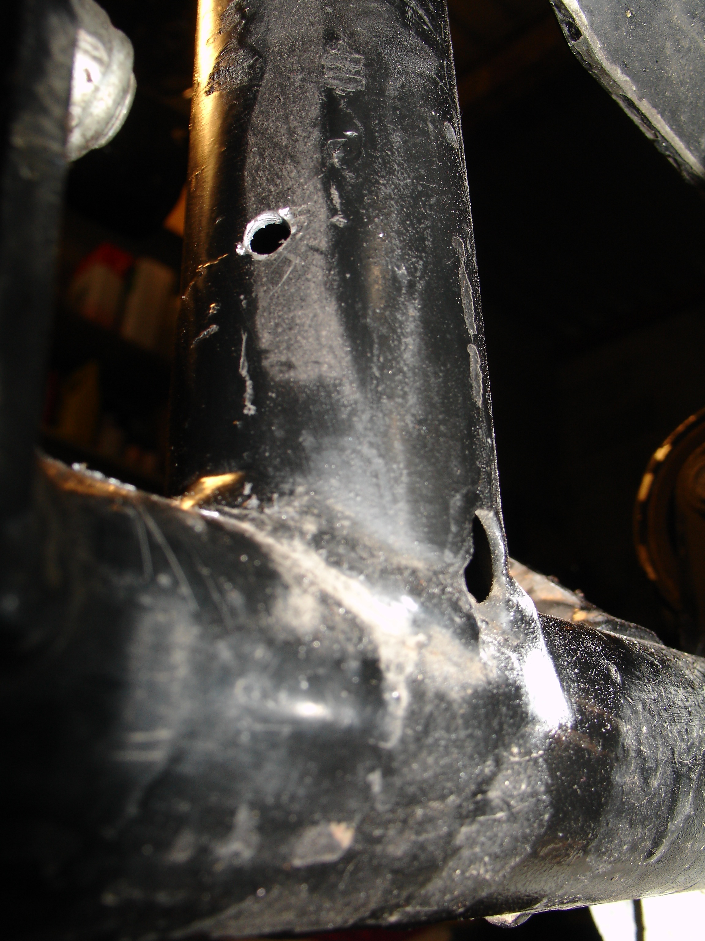
A HOLE IS THEN DRILLED JUST BEYOND EACH END OF THE CRACK.
The first step is to drill a hole just beyond each end of the crack to prevent further propagation. Then use silver brazing alloy to re join the parent metal along the crack after which all oxidisation must be removed from the
whole area before a load spreading plate is fitted over the tube covering the area of the crack.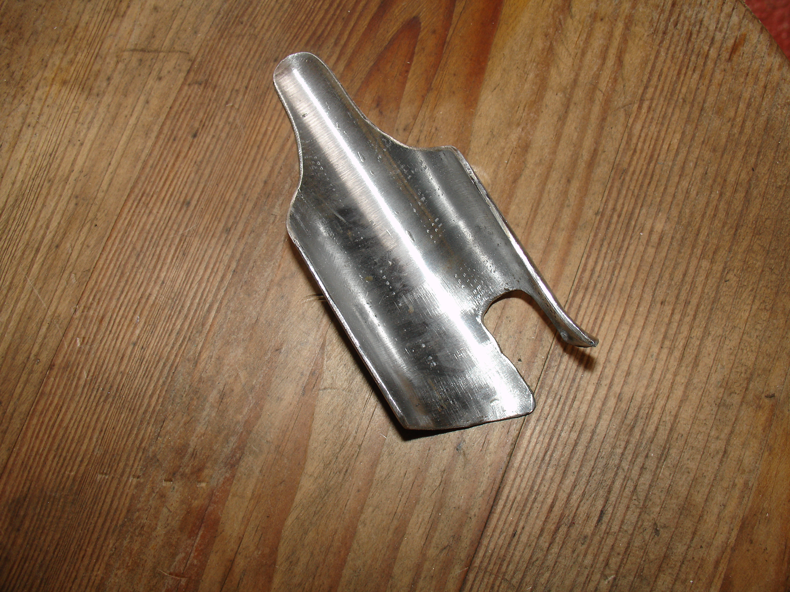
LOAD SPREADER MADE FROM SLIGHTLY LARGER DIAMETER TUBE TO COVER A LARGER AREA THAN THE CRACK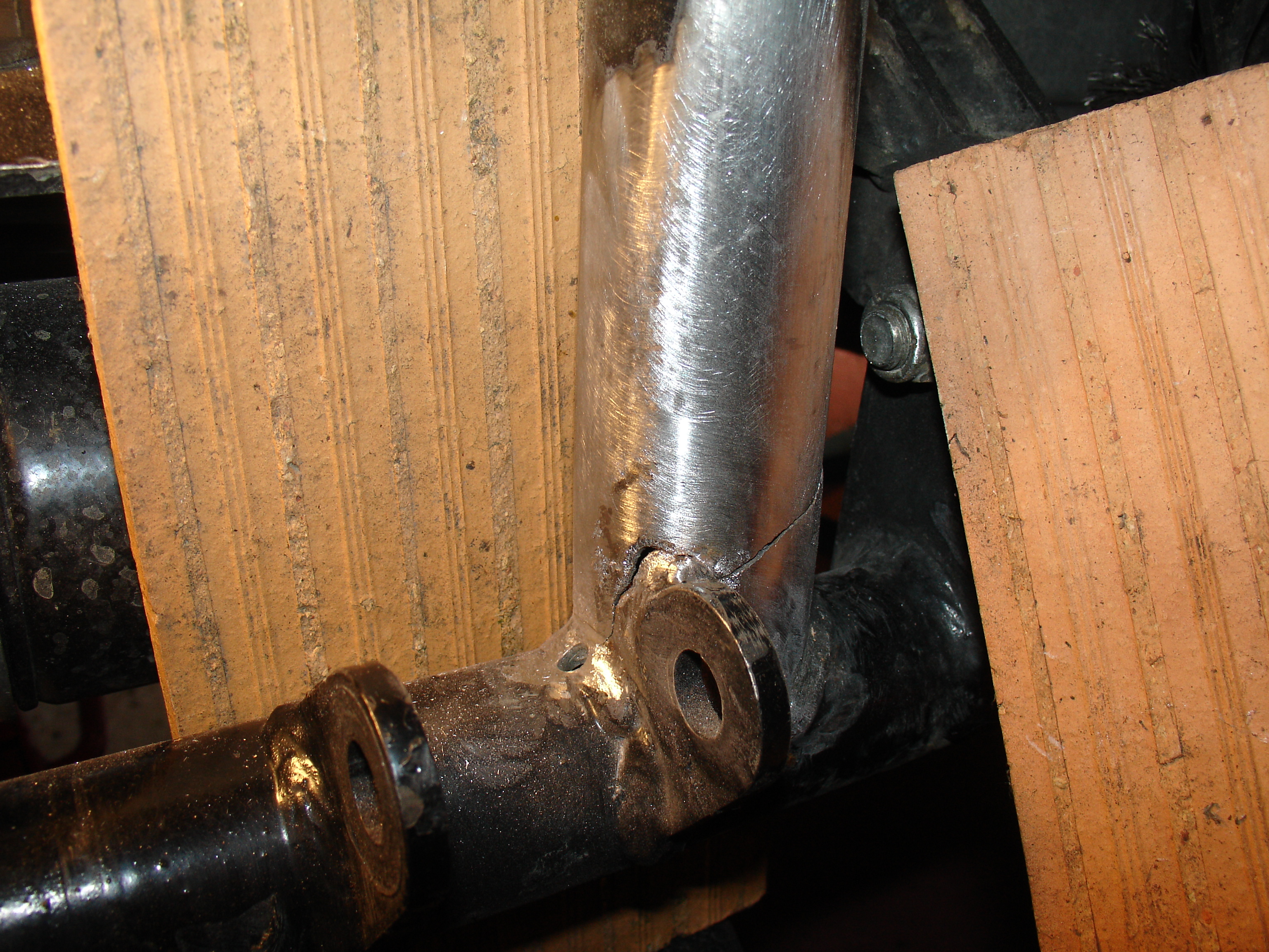
THE TUBE PREPARED BY MECHANICAL REMOVAL OF ALL PAINT AND THEN DEGREASED WITH ACETONE
Note the ceramic tiles used as heat shields to prevent damage to the surrounding area
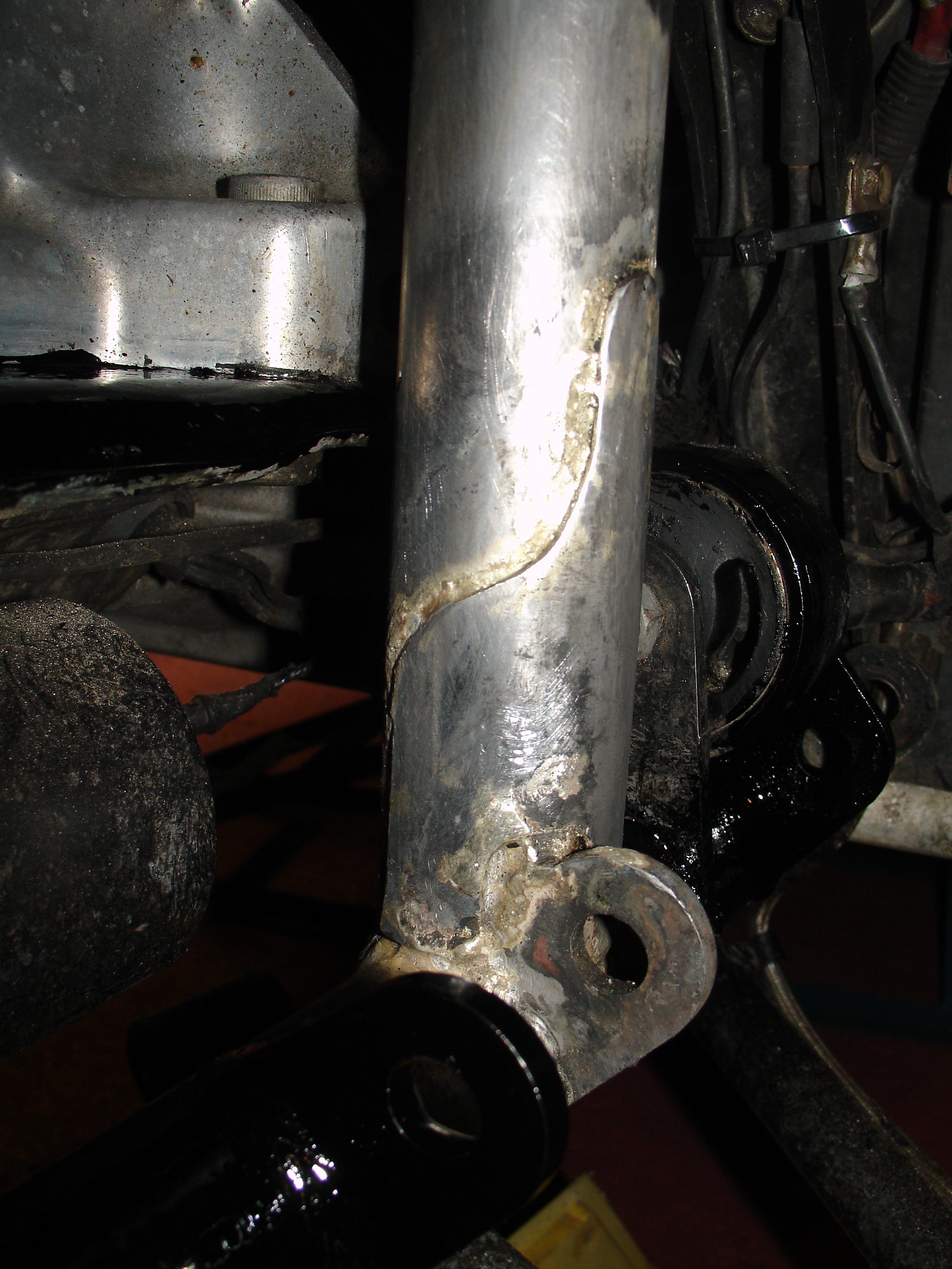
THE LOAD SPREADER BRAZED IN PLACE AND CLEANED UP PRIOR TO PAINTING
Having carried out the repair to the cracked chassis I have decided to do some preventative stress relieving on the other, off, side. My crack was on the near (left) side but I have seen others on the right so I expect trouble there too.
I believe the cracks to be due to stresses in the tubes set up by the welds cooling and also due to the heat affected area adjacent to the welds.
THE COOLING FAN
From day one the cooling fan on my machine has never worked - I had professionals re program the ECU but still it never worked. I have always hated the plastic nonsense in which the fan is mounted and particularly the
fact that it is only fastened with two bolts at the top and the rest of it just hangs down behind the cylinders. two lengths of split rubber hose were slotted over the edges of the plastic to prevent it from chafing the fins - poor to say the least.
I ran the fan with an electric by pass to see how it performed and noted that no air was blown through between the cylinders just at the outside edges, there is a deflector plate which I believe helps to get air around the back of the cylinders
but it completely prevents air from the fan from passing through between the cylinders. I didn't think this was too clever and decided to do some more research. the front edge of the bonnet creates what railway enthusiasts will know as an
air dam - making the area between the grille and the cylinders almost still so the deflector in the plastic shroud serves no purpose anyway. I decided to do away with it and ran for a while with no fan at all - needless to say I suffered
overheating in traffic especially when the weather was hot.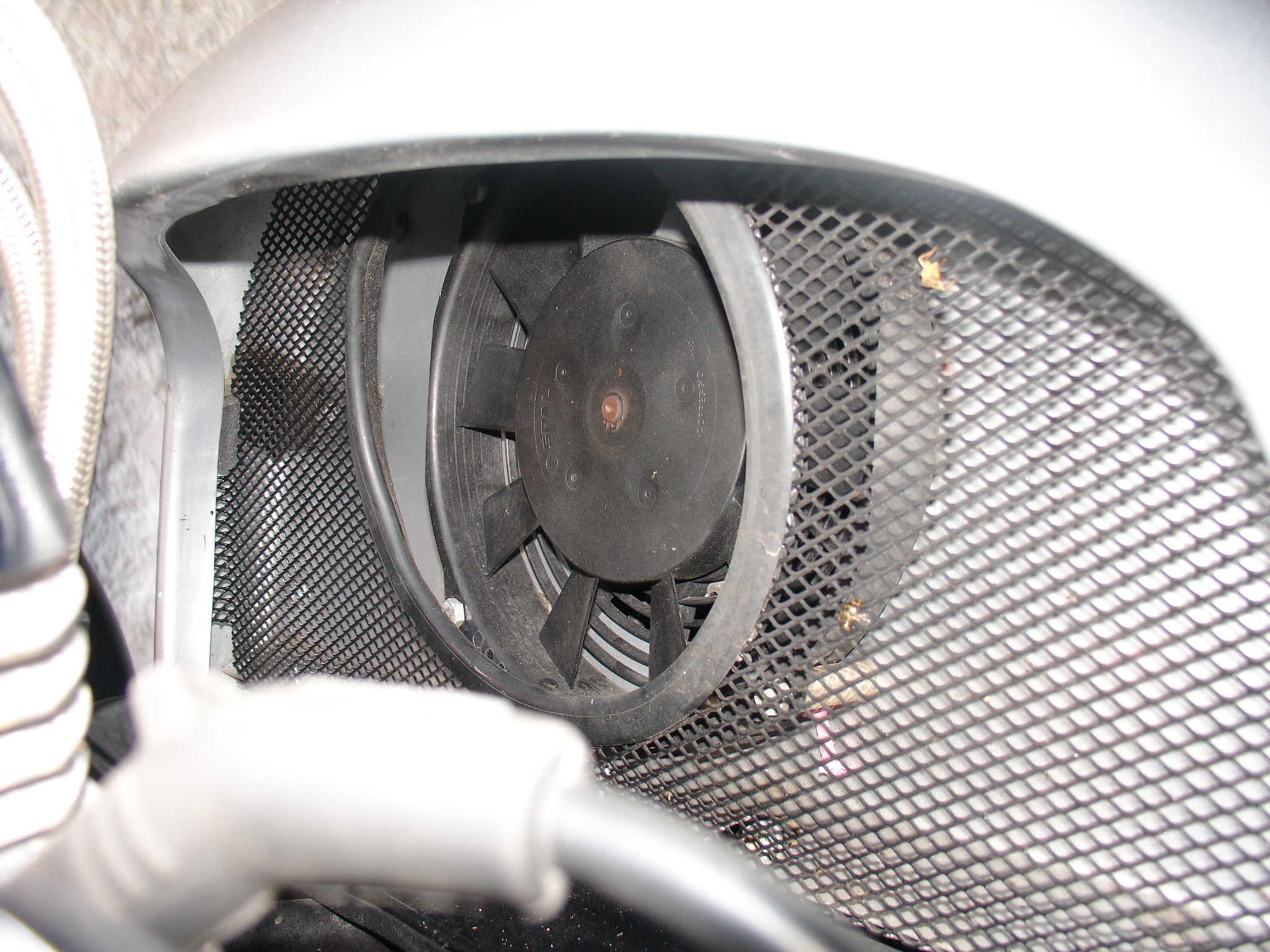
THE FAN IN PLACE BEHIND THE GRILLE
NOTE THE PLASTIC EDGE TRIM ON THE MESH
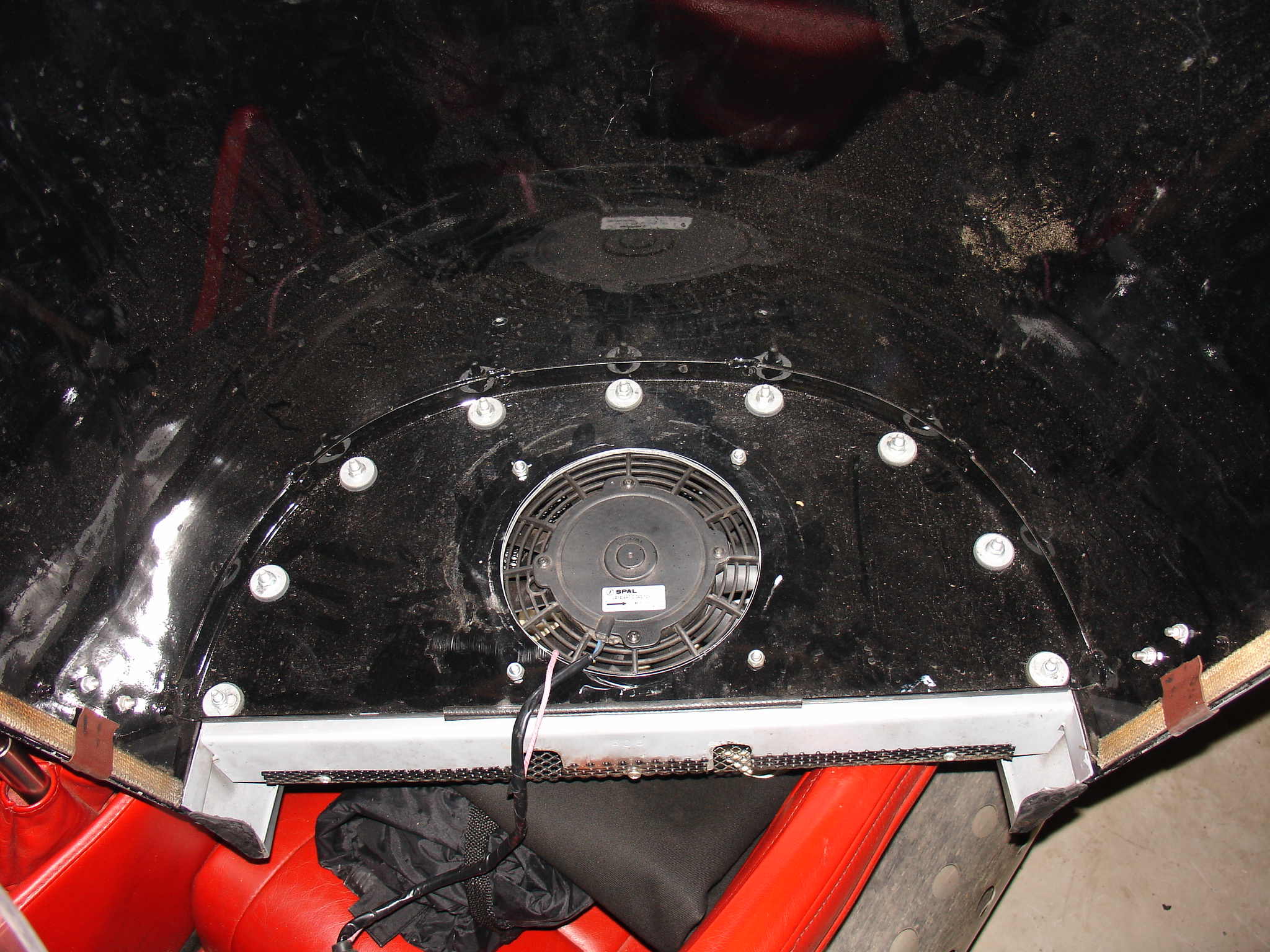
THE FAN FROM INSIDE THE BONNET
SHOWING THE CUT OUT IN THE PANEL
BACK TO TOP OF PAGE
IMAGE GALLERY:-
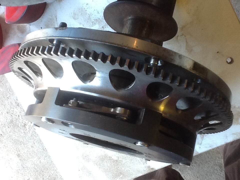
A view of the clutch
Morgan three wheeler
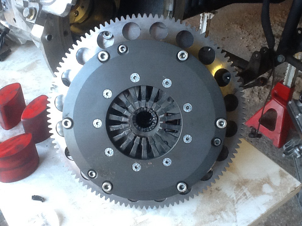
A view of the clutch
Phil and Claire Bleazey
At The Old Furness Street Stables
LANCASTER
LA1 5QZ
Tel:- 0044 (0)1524 849085
Last Updated November 2022
Morgan three wheeler drive train
Morgan three wheeler compensator
Morgan three wheeler drive quality
Morgan three wheeler bevel box
P.G.Bleazey drive train upgrade kit